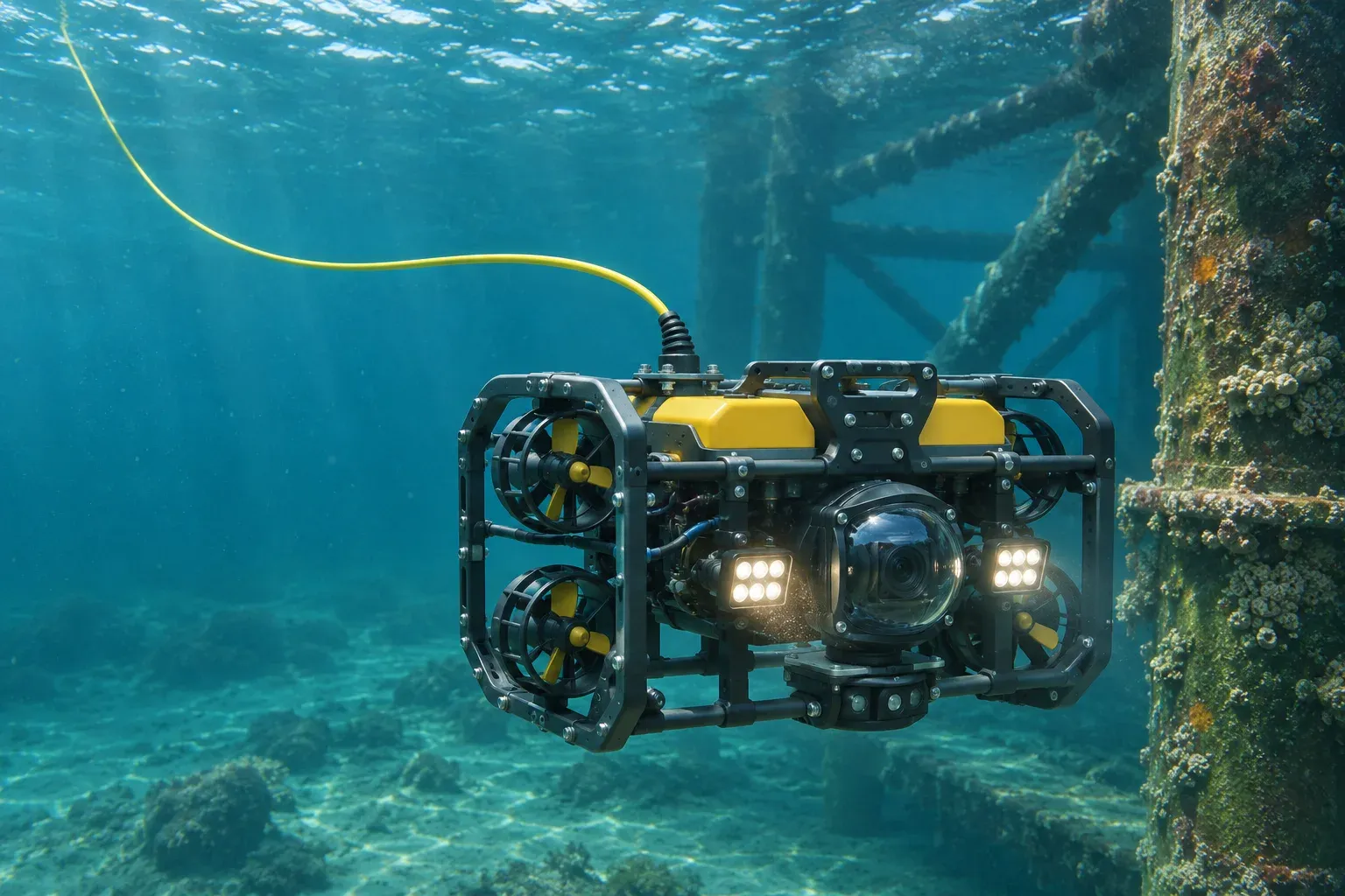
A marine engineering team preparing an inspection ROV needs a long fiber optic tether that stays close to neutral buoyancy, carries video and telemetry reliably, withstands recovery loads and mates with the vehicle’s subsea interface. A cable that meets the optical specification on a reel can still prove unsuitable if its termination takes the pulling load through the connector or its buoyancy changes at operating depth.
Specify the system from the topside optical equipment and winch to the vehicle’s optical port and mechanical attachment point. This guide explains how to define the cable, both ends and the acceptance tests in one RFQ. DEV CABLE’s custom neutrally buoyant ROV tether cables provide a starting point for the cable design review.
Why Fiber Optic ROV Tether Design Matters
An optical link can carry long-distance video, control commands, telemetry and sensor data between a remotely operated vehicle and its topside equipment. A fiber-only tether carries communications. The vehicle needs a separate power source, such as onboard batteries. Confirm whether the optical equipment uses a single bidirectional fiber or separate fibers for transmit and receive.
All else equal, a smaller cable diameter presents less area to a cross-current and can reduce drag. Payout length, current speed, cable shape and heading also affect the force the thrusters must overcome. Near-neutral buoyancy reduces the tether’s apparent weight in water. Drag remains, and the tether can still be swept toward structures or create a load at the vehicle attachment.
Review transit, working and recovery conditions separately. A smaller diameter can limit room for the strength members or buoyancy material, while a thicker tether can consume drum capacity. The specification should reflect the vehicle’s thrust margin, the intended payout and the loads at launch, during operation and during recovery.
Understanding a Complete ROV Fiber Optic Tether Cable Assembly
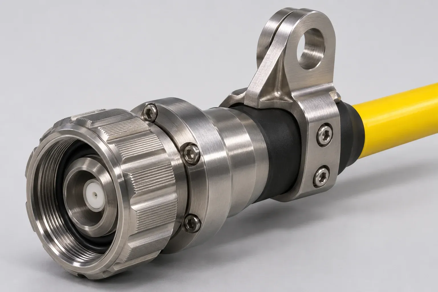
Review three elements together. The tether cable provides the optical path, distributed buoyancy and strength members. The underwater fiber optic connector provides a separable optical interface and a defined pressure or sealing boundary. The mechanical strain relief and stress termination manage bending and transfer tensile load into the designated attachment point. A flexible boot controls the exit bend. The axial load needs a termination that engages the strength members.
Unterminated cable is supplied without installed end fittings. A connectorized cable has one or both connectors installed. A fully engineered assembly has defined end interfaces, seals, load paths and acceptance criteria for the completed configuration. State which scope the buyer needs at each end. For instance, the vehicle end may need a subsea cable-end plug and frame anchor, while the topside end connects to a reel or enclosure. Review how water is kept out at the cable entry, how optical loss is measured and where tensile load enters the frame or winch.
Single-Mode Fiber Optic Cable Construction
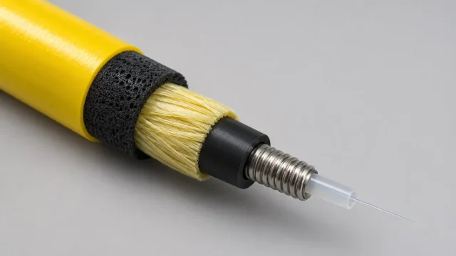
One possible fiber-only design uses the following layers, listed from the center outward. Their dimensions and order depend on the cable’s mechanical, pressure and buoyancy requirements.
- Single-mode optical fiber provides the data path. Select the fiber type and test wavelengths with the transceivers and any reel-mounted optical hardware.
- Loose tube protects the fiber and allows controlled movement so cable strain is less readily transferred to the glass.
- Optional stainless steel spiral provides localized mechanical protection around the optical unit. Evaluate its mass, stiffness and bend behavior before including it.
- HDPE inner jacket forms a protective sheath around the optical unit and a bedding layer for the reinforcement.
- Aramid reinforcement yarn carries axial loads when captured by a compatible stress termination. Yarn layout and anchoring affect how the load is distributed.
- Foamed polyurethane layer lowers the average density of the cable. Its density, thickness and resistance to compression affect the usable buoyancy range.
- Tough yellow polyurethane outer jacket provides a visible wear surface. Specify the required abrasion resistance and compatibility with the water, handling equipment and expected exposure.
Review longitudinal water blocking separately if the system must limit water migration after jacket damage. The cable build and its end seals both affect that behavior.
How Neutral Buoyancy Is Achieved
A submerged tether experiences an upward force equal to the weight of the water it displaces. For a uniform cable, compare the cable mass per meter with the mass of the water displaced by one meter of cable. Equal masses give approximately zero net vertical force. Less cable mass produces positive buoyancy. The cable displaces more mass in seawater than in freshwater at the same displaced volume because seawater is generally denser. NOAA’s explanation of seawater density
Specific gravity compares the cable’s average density with a reference water density. A value near 1.0 is meaningful only with the reference conditions stated. Agree on water type, salinity, temperature, pressure and acceptable apparent weight per meter. Changes in foam density, jacket thickness, steel content or aramid reinforcement can move the cable across that tolerance. At depth, foam compression may reduce displaced volume and therefore buoyancy.
Specify the bare cable’s buoyancy and assess the finished assembly separately. Metal connectors and anchors can cause localized downward loading even when the long cable span is close to neutral. If the vehicle needs a slight upward bias or a limit on end load, define it under the expected service conditions.
Selecting Underwater Fiber Optic Connectors
Start with the mating part number and drawing at each end. Confirm single-mode fiber type, channel count, optical interface or polish where applicable, keying, coupling and sealing geometry. A bulkhead connector mounts through an enclosure or panel. A cable-end connector terminates the tether. Identify the exact mating pair, since a shared family name or shell diameter alone cannot establish compatibility.
A dry-mate connector is connected in dry conditions before deployment. A wet-mate connector can be connected underwater under the conditions qualified by its manufacturer. Check the allowable mated and unmated pressures, mating conditions and cycles, cap requirements and cable-entry seal. Corrosion-resistant shell options can include 316L stainless steel. Review suitability with the mounting materials and water chemistry, then check the pressure qualification of the exact connector and cable termination. TE Connectivity’s overview of subsea fiber interfaces
Specify a maximum insertion loss for each mated pair at the operating wavelengths. For positive return loss (RL), use a minimum where applicable, such as RL ≥ 40 dB for a defined interface. A larger positive value represents less reflected power. If the vendor uses negative event reflectance, state that convention explicitly. Also distinguish a connector-level reflection limit from the optical return loss of the whole link. Corning’s optical loss definitions
Tensile Strength, Strain Relief and Cable Handling
The safe working load (SWL) is the allowable load under defined service conditions. Minimum breaking strength is a separate destructive-test threshold. Ask for both, along with the load cases and design basis. The complete assembly’s allowable load is bounded by its weakest qualified load-bearing component, including the cable, stress termination and attachment hardware. The stress termination should route tension from the aramid members into the designated mount and protect the optical interface from that load.
Specify a static bend radius for installed or stored cable and a dynamic bend radius for payout, recovery and repeated flexing. Check drum core, sheaves, fairleads, approach angle and winding tension against the dynamic limit. Repeated bending under tension can cause fatigue or increased optical loss. Agree on representative loads, cycle counts, bend radii and optical acceptance limits for mechanical testing. Include startup, recovery and vessel motion where they create meaningful peak loads.
Example: Specifying a Long-Length Single-Mode ROV Tether
These values illustrate a project-specific buyer specification. They are not universal ROV tether ratings or confirmed DEV CABLE product performance. Final values require engineering review and validation.
| RFQ parameter | Illustrative buyer requirement |
|---|---|
| Cable length | Approximately 500 m |
| Optical fiber | One single-mode fiber |
| Cable outside diameter (OD) | 9.0 ± 0.3 mm |
| Specific gravity target | 1.0 ± 0.03, reference and test conditions to be agreed |
| Cable safe working load | Approximately 130 kgf |
| Stress termination working load | 200 kgf, subject to qualification |
| Outer jacket | Yellow polyurethane |
| Fiber attenuation at 1310 nm | ≤ 0.45 dB/km |
| Fiber attenuation at 1550 nm | ≤ 0.35 dB/km |
| Hydrostatic qualification test | 5 MPa (50 bar), two-hour hold |
At the nominal 500 m (0.5 km) length, the maximum fiber-only attenuation is 0.225 dB at 1310 nm (0.45 × 0.5) and 0.175 dB at 1550 nm (0.35 × 0.5). These values exclude connector, splice and other system losses. Calculate the full budget using the maximum installed length, all mated pairs and splices, any optical rotary joint and an agreed margin.
A 200 kgf termination target cannot raise the cable’s approximately 130 kgf working load. Other qualified components and the actual duty can further constrain the assembled system. The 50-bar hold defines one hydrostatic test condition. A continuous operating-depth rating requires separate qualification for the specified configuration, exposure time and pressure cycles.
Testing and Quality Requirements
Agree on the test article, method, conditions, pass limits and required reports before production. Identify which checks qualify a design and which apply to each finished assembly or to a sample.
- Fiber attenuation measures distributed optical loss at specified wavelengths, typically expressed in dB/km. An end-to-end measurement of the finished link is expressed in dB and includes the defined interfaces.
- Connector insertion loss measures the loss introduced by the mated interface against an agreed reference. Return loss quantifies light returned from the specified interface or link.
- Optical time-domain reflectometry (OTDR) locates events such as splices, bends and reflections along the fiber. Select launch and receive fibers and settings that resolve the ends of the tether. Use a referenced source and power meter where required for end-to-end loss acceptance. EXFO’s OTDR launch and receive fiber guide
- Hydrostatic testing checks the agreed configuration at the specified pressure, hold time and cycles. Define what to inspect or measure during and after exposure, such as leakage and change in optical loss.
- Tensile testing checks load transfer, slippage and optical stability under load. Define any proof-load and destructive qualification tests separately.
- Buoyancy verification measures apparent weight or upward force under defined water and pressure conditions. Bend and spooling endurance testing checks the tether after repeated handling at representative radius and tension.
- Final assembly inspection confirms length, diameter, end configuration, optical end-face condition, markings, protective caps and completeness of test records.
What to Include in Your ROV Tether Cable RFQ
Copy this checklist into your inquiry and mark any values still open for engineering review.
- ROV application — vehicle, inspection task and optical equipment at both ends.
- Operating depth — routine and maximum depth, exposure duration and cycles.
- Water type — freshwater, seawater or brackish water, with salinity and temperature where known.
- Cable length — per assembly, measured between specified points, with tolerance.
- Fiber — single-mode grade, fiber count and transmit/receive arrangement.
- Optical limits — wavelengths, attenuation, end-to-end loss budget and reflection limits.
- Maximum OD — tolerance and any clearance, drum or gland constraints.
- Buoyancy — target and tolerance, test conditions and acceptable end loads.
- Mechanical loads — working and breaking loads, units and deployment load cases.
- Bend radii — required static and dynamic limits and available routing space.
- Connectors — drawings, mating part numbers, panel or cable-end requirements and wet- or dry-mate duty for each end.
- Strain relief — mounting geometry, bend protection and axial load path.
- Deployment — payout and recovery method, drum and sheave sizes, and cycling frequency.
- Testing — methods, acceptance criteria, test reports and witness requirements.
- Commercial details — quantity, delivery destination and required delivery date.
Frequently Asked Questions
What is a neutrally buoyant ROV tether cable?
It is a tether designed to have near-zero apparent weight per unit length in defined water conditions. Check whether the requirement covers the bare cable span, the finished assembly or both.
Is single-mode fiber suitable for long ROV tethers?
Yes, when the transceivers, wavelengths and link budget suit the run. Include optical losses from the terminations and any splices or rotary joint before selecting the optics.
Can a fiber optic tether be customized for seawater?
Yes. Set buoyancy for the expected salinity, temperature and depth. Review jacket, seals and termination materials for the same service environment.
How are underwater fiber optic connectors selected?
Identify the equipment’s exact mating interface, then confirm optical performance, pressure and mating conditions. Check the proposed cable-entry seal and end fitting with the selected cable diameter and jacket.
How does cable working load differ from termination strength?
Cable working load applies to the cable under defined conditions. Termination strength applies to the hardware and anchoring method under its own test conditions. Use comparable service ratings when evaluating the assembly’s load limit.
What information is needed for a custom quotation?
Start with length, water type and depth, fiber count, buoyancy and loads, both end interfaces, and quantity. Send mating drawings and acceptance criteria as soon as they are available.
Custom ROV Fiber Optic Tether Solutions from DEV CABLE
DEV CABLE engineers and manufactures custom ROV tether cables. Fiber count, cable construction, diameter, reinforcement, buoyancy target, jacket material and length can be reviewed against the application and confirmed during engineering. For connectorized assemblies, DEV CABLE reviews interface selection, termination feasibility and the required qualification before quotation.