Available Crane Pendant Control Cable Models
DEV CABLE manufactures a range of steel wire reinforced crane pendant control cables for electric hoists, overhead cranes and industrial lifting equipment. Flexible multicore copper conductors carry the control circuits, while integrated steel support members provide the intended mechanical suspension path through correctly designed terminations.
The following six models are commonly available manufacturing configurations confirmed by our manufacturing team. Beyond these models, we support flexible customization for equipment-specific requirements.
| Model | Core Configuration | Steel Support Structure |
|---|---|---|
| DC-PC-0815 | 8 × 1.5 mm² | Double Steel Wire |
| DC-PC-1215 | 12 × 1.5 mm² | Double Steel Wire |
| DC-PC-1615 | 16 × 1.5 mm² | Double Steel Wire |
| DC-PC-2015 | 20 × 1.5 mm² | Double Steel Wire |
| DC-PC-2415 | 24 × 1.5 mm² | Double Steel Wire |
| DC-PC-08075 | 8 × 0.75 mm² | Single / Double Steel Wire |
These are confirmed manufacturable products. Stock availability, model-specific ratings, dimensions and delivery terms are confirmed with the quotation. Use the equipment wiring diagram to identify control circuits, any protective conductor and spares; do not infer these from the model code or the number of push-buttons alone.
This is a pendant control cable, not a general-purpose power feeder. It also serves a different duty from a flat festoon cable traveling along a crane beam. Its flexibility and steel reinforcement do not establish suitability for continuous reeling, drag chains, repeated torsion or lifting a crane’s working load.
Cable Construction: Dual Steel Support Members
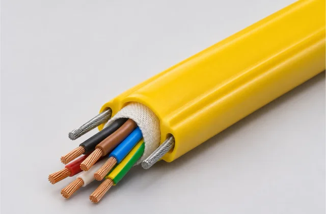
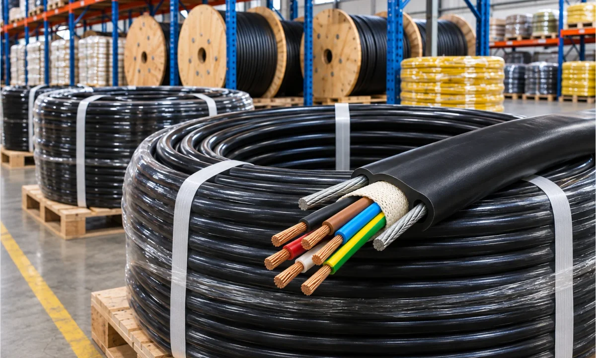
The supplied hero cutaway shows a yellow outer sheath, individually insulated stranded copper cores, a textile-looking wrap and two steel support members on opposite sides of the core bundle. The black cutaway in the handling image shows the same general dual-support arrangement. These views explain the reference layout; an order drawing defines the exact materials and dimensions.
| Component | Construction and purpose |
|---|---|
| Flexible stranded copper conductor | Carries the electrical control circuit. Specify conductor cross-section, stranding and terminal requirements; appearance does not confirm annealing or conductor class. |
| Individual core insulation | Separates the electrical cores. The compound, thickness and ratings must match the confirmed control-circuit specification. |
| Core identification | Colors are visible in the supplied cutaway. Agree the ordered color code or numbering, including any protective conductor, against the wiring diagram. |
| Wrapping and any fillers | A light textile-looking wrap surrounds the pictured core bundle. Confirm its actual material and any required fillers or binders in the construction drawing. |
| Two lateral steel support members | Provide the mechanical suspension path when anchored to suitable fittings. Wire construction, dimensions, strength and termination details require confirmation. |
| Protective outer sheath | Encloses the core assembly and support channels. Confirm the compound, profile, dimensions, color and compatibility with the installation environment. |
Support wires and termination design
The steel members perform a mechanical support function. They must not be used as control-circuit conductors or as a substitute for a specified protective earth conductor. The copper cores must remain free of the pendant’s suspension load at both terminations.
Support-wire count alone does not determine a permissible load or hanging length. The complete design must account for the pendant mass, suspended cable mass, movement, anchorage, load sharing and any applicable installation requirements. Have the support system and terminations checked for the intended equipment; a cable gland must not be assumed to anchor the steel members unless it is designed for that function.
Single versus double steel wire pendant cable
The product pictured here uses double steel support wires. DC-PC-08075 (8 × 0.75 mm²) can be manufactured with single or double steel support wires; the five listed 1.5 mm² models use double steel wire. Custom support arrangements can also be specified according to the mechanical suspension requirement.
Single and double support arrangements require the corresponding cable and termination design; they are not automatically interchangeable at the equipment’s anchors. Two wires do not establish twice the allowable load.
Applications of Crane Pendant Control Cable
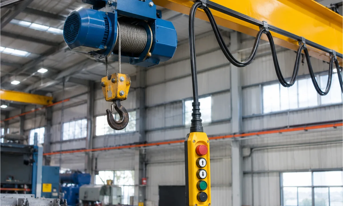
The pendant drop connects a hanging push-button station to the hoist or crane control system. The application image above illustrates that connection beside an electric hoist; the loops running along the beam are a separate traveling cable arrangement.
- Electric hoists: pendant stations carrying the specified hoist control circuits between the operator and the hoist equipment.
- Overhead bridge cranes: suspended controls where the electrical and support design matches the crane’s pendant arrangement.
- Gantry cranes: pendant connections selected with outdoor exposure and movement requirements explicitly reviewed when applicable.
- Jib cranes: hanging control stations with routing and clearance appropriate to the equipment’s working area.
- Pendant push-button control stations: multicore connections selected from the station wiring diagram, enclosure entries and suspension fittings.
- Industrial lifting equipment: OEM or replacement pendant wiring where the complete cable construction is accepted for the equipment.
Pendant drop versus traveling festoon system
A pendant cable supports a suspended control connection through its designed support members and anchors. A festoon system carries a traveling cable in loops on trolleys or other supports along a rail or beam. A cable suitable for one arrangement is not automatically suitable for the other. Specify the actual route, movement and support method rather than choosing by the word “crane”.
For fixed control wiring elsewhere in the installation, review CVV-S shielded control cable. For tray-based plant power or control routes, review TC-ER tray cable. Neither family name establishes the mechanical support needed for a suspended pendant drop.
Flexible Custom Crane Pendant Cable Manufacturing
Different crane systems and electric hoists require different cable configurations. The six listed models are a starting range, not the limit of DEV CABLE’s manufacturing scope. We offer flexible custom crane pendant cable manufacturing around your control-circuit requirements, suspension design and installation environment.
Custom Core Configurations
Different numbers of conductors can be manufactured to match the equipment’s electrical control requirements. Specify the circuit connections, spare cores, any protective conductor and the required color code or numbering from the wiring diagram.
Custom Conductor Sizes
Select conductor cross-sections in mm² according to the required electrical specification and equipment terminals. Copper stranding, finish, annealing and conductor-class requirements can be included in the custom specification; the proposed construction must satisfy the agreed circuit requirements.
Single or Double Steel Support Wires
Steel support arrangements can be customized according to the mechanical suspension design. Specify the wire construction, dimensions, required mechanical properties, suspended loads and anchorage interface so the cable and its terminations can be agreed together.
Jacket and Cable Construction Options
Customize insulation, jacket material, color and overall construction around the project environment and manufacturing feasibility. Include temperature, oil, moisture, UV, abrasion or chemical exposure; finished body and support-channel dimensions; gland entry; marking and traceability requirements. Materials and environmental performance are confirmed for the selected construction.
Flexible MOQ & OEM Supply
DEV CABLE supports flexible minimum order quantities and OEM manufacturing for crane builders, distributors and maintenance teams. The order minimum depends on the agreed cable construction, materials and required quantity. Material availability, packing, production and delivery terms are confirmed in the quotation.
Need a Different Crane Pendant Cable Configuration?
Can’t find the exact cable specification you need? DEV CABLE offers flexible customization for crane and electric hoist pendant control cables, including custom core counts, conductor sizes, steel support wire configurations and cable lengths. Send your technical requirements for a tailored quotation.
Selecting the Electrical and Suspension Design
Use the circuit drawing and equipment layout together. Confirm required cable voltage, conductor size and insulation with the electrical design; confirm the suspension and support terminations with the equipment’s mechanical design. Do not infer either from jacket color or a similar-looking replacement cable.
| Selection question | Information needed before acceptance |
|---|---|
| Does the cable match the pendant circuit? | Wiring diagram, circuit voltage, required cable rating, core count, conductor size and protective-conductor arrangement. |
| How is the assembly suspended? | Pendant mass, cable mass/length, free-hanging drop, support-wire design, upper and lower anchors and termination drawings. |
| What movement will occur? | Bending, swinging, handling and any torsion, with the intended operating pattern. Flexible construction alone does not establish a cycle-life rating. |
| What will contact the sheath? | Temperature, indoor/outdoor location, sunlight, water, oils, chemicals, abrasion and cable-entry constraints. Confirm required resistance with model-specific evidence. |
| What documents are required? | Agreed construction drawing, datasheet, dimensions, installation limits, applicable standards and any required approval/test documentation for the exact proposed model. |
No universal voltage, temperature, minimum bend radius, cycle life, suspended height, load limit or support-wire tensile strength is published for this custom family. Obtain those values for the selected design before finalizing the installation. A requested UL, CE, CSA or other approval must be reviewed with matching documentation; no approval is asserted on this page.
Request a Quote for Custom Crane Pendant Control Cable
Send your cable specification, application details and quantity to DEV CABLE using Request a Quote on this page. The existing inquiry form opens with a pendant-specific checklist; email and WhatsApp are also available.
- Equipment type and pendant model, with a wiring diagram or replacement cable drawing if available.
- Required cable model or custom configuration, including the single or double support choice where applicable.
- Number of cores, including spare cores and any protective conductor; conductor cross-section and stranding.
- Control-circuit voltage and required cable voltage rating.
- Total cable length, suspension height/free-hanging drop and required cut lengths.
- Pendant mass, other suspension loads, single or double support wires, and anchorage details.
- Installation environment, operating temperature, bending/movement and exposure conditions.
- Insulation, sheath, finished dimensions, jacket color, core identification and marking requirements.
- Estimated order quantity, packing, destination and requested delivery date for confirmation.
- Required standards, certifications and supporting documents, identifying any mandatory acceptance conditions.
Every finished DEV CABLE cable length undergoes 100% electrical continuity testing before shipment. Additional electrical tests, mechanical qualification and project acceptance documents must be agreed separately; continuity testing does not establish a suspension rating or certification.
Frequently Asked Questions
What is a crane pendant control cable?
It is a flexible multicore cable connecting a suspended push-button station to a crane or electric hoist control system. In the pictured design, two integrated steel support members provide the mechanical suspension path through suitable anchors, while the copper cores carry the electrical control circuits.
What is the purpose of steel support wires in a pendant cable?
They transfer the intended suspension loads to the designed support fittings so those loads are not carried by the electrical cores. Permissible load and hanging length depend on the complete cable, pendant, movement and termination design; a visible steel wire is not a load certificate.
What is the difference between single and double steel wire pendant cables?
They use different support arrangements. DC-PC-08075 (8 × 0.75 mm²) is available with single or double steel support wires; the five listed 1.5 mm² models use double steel wire. The supplied images illustrate two lateral members. Wire count alone does not establish strength, load sharing or interchangeability with the equipment’s existing anchors.
How many cores are required for an electric hoist pendant cable?
Use the equipment wiring diagram to count the required control connections, any protective conductor and specified spares. The number of push-buttons alone does not establish the core count, conductor size or protective-conductor requirement.
Can crane pendant control cables be customized?
Yes. The six confirmed models are a starting range. For a different construction, send the wiring diagram, required core count, conductor size in mm² and support arrangement. See the customization options for the other details to specify.
How does pendant control cable differ from festoon cable?
Pendant cable serves the hanging control-station connection. Festoon cable travels in supported loops along the crane route. Specify each duty separately; this pendant design must not be assumed suitable for traveling festoon systems or drum reeling.
What information is required to request a quotation?
Identify the required model or custom configuration, then provide equipment and circuit drawings, cores and conductor size in mm², voltage requirement, cable length and suspension height, pendant load, single or double support-wire/anchor details, movement, environment, materials, quantity, packing and destination. Include required standards and approval documents so unresolved specifications can be addressed before the proposed cable is accepted.