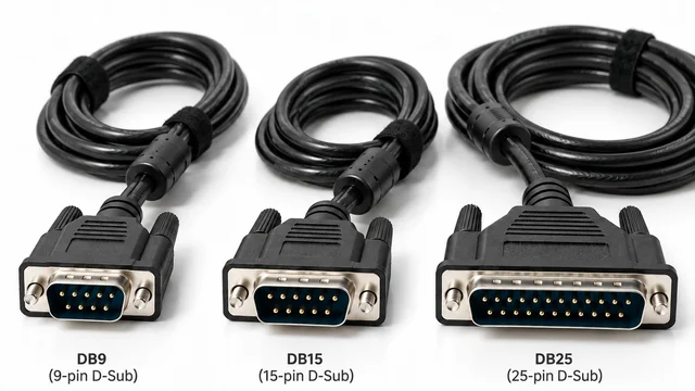
“DB15 male to DB15 male, 15 m” describes the ends and length of a cable. It does not tell a manufacturer how to wire it. For procurement managers, engineers, maintenance teams and OEM buyers, that missing information can determine whether an assembly works at commissioning.
A custom D-Sub cable specification must connect the mechanical interface to the electrical design: pin assignment, physical pairs, shielding, grounding, signal requirements and termination details. Three principles should guide the purchase:
Same connector does not mean same pinout. Correct continuity does not necessarily mean correct pair assignment. Double shielding does not automatically guarantee EMC performance.
Why the Connector Alone Does Not Define a D-Sub Cable
The familiar nine-contact connector is commonly called DB9, although DE-9 is the more precise designation. Buyers also encounter 15-pin D-Sub and DB25 connectors, with male pin contacts or female socket contacts. Record the contact gender at both ends rather than relying on equipment labels such as “input” or “output.”
Identical connector housings can contain straight-through wiring, crossed wiring or a fully custom map. One assembly might carry serial data; another might carry alarm contacts, encoder signals or auxiliary power. Shape and contact count establish neither voltage compatibility nor a communication protocol.
Check the equipment interface before substituting a cable that physically fits.
What Is a D-Sub Pin Assignment?
A pin assignment defines which electrical circuit reaches each numbered contact. Connector designations such as X1 and X2 identify the ends; pin numbers identify contact positions. Signal names describe electrical functions, while conductor colors and pair numbers identify the wires used to carry them.
The shield is the conductive screen around the cable; the shell is the connector’s metal enclosure. Neither is automatically signal ground. “NC” means no connection at the specified position.
Example only — actual pin assignments are project-specific.
| X1 contact | X2 contact | Signal | Conductor | Physical pair |
|---|---|---|---|---|
| Pin 1 | Pin 1 | Signal A+ | White, pair 1 | 1 |
| Pin 2 | Pin 2 | Signal A− | Blue | 1 |
| Pin 3 | Pin 3 | Signal B+ | White, pair 2 | 2 |
| Pin 4 | Pin 4 | Signal B− | Orange | 2 |
Repeated white conductors make the pair identifier essential. “White wire to pin 1” is ambiguous if several pairs contain white wires. Define identification at both ends and preserve it during assembly.
Why Pin Numbering and Viewing Direction Matter
Looking into the mating face and looking at the rear termination side produces mirrored layouts. A drawing copied without its viewing direction can therefore create a consistently wrong cable.
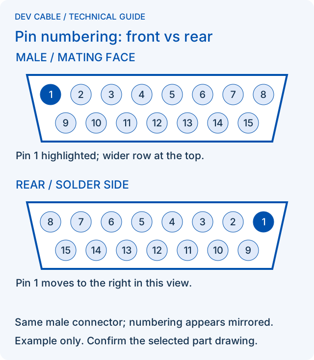
Specify gender, contact count, row count, viewing direction and the connector manufacturer’s numbering reference. Use an explicit note such as “Pin numbering shown from mating face.” For a rear termination illustration, label that view separately.
The diagram shows one male two-row 15-pin connector in two views, with its wider row kept at the top. It is not a female connector drawing or a universal assembly instruction. Check the selected part’s drawing and molded contact numbers before wiring.
Straight-Through, Crossed and Fully Custom Wiring
Three descriptions commonly appear in RFQs:
- Straight-through: matching positions connect, for example 1 → 1, 2 → 2 and 3 → 3. Specify whether this includes every contact and the shells.
- Crossed: selected positions exchange, for example 1 → 3, 2 → 2 and 3 → 1. This illustration is not a standard serial crossover pinout.
- Fully custom: the equipment defines the map, such as X1.1 → X2.8 and X1.2 → X2.4, with other contacts assigned individually.
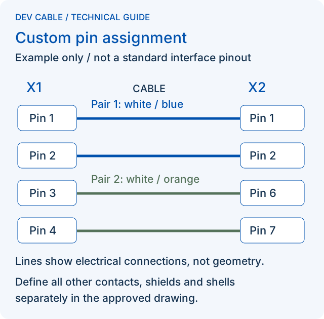
This diagram is a separate custom example from the straight-through table above. A purchase specification must choose one complete, controlled wiring definition. Descriptions such as “standard DB cable assembly” leave too much room for interpretation.
Pin Assignment Is More Than Pin-to-Pin Continuity
A continuity test can confirm that X1.1 reaches X2.1 without establishing which physical pair carries that circuit. Two assemblies with the same DC connection map can have different noise behavior.
For a differential signal, keep its two conductors within the same physical twisted pair unless the interface specification explicitly requires otherwise:
- Correct grouping: A+ uses the white conductor of pair 1; A− uses its blue partner.
- Split pair: A+ uses white from pair 1; A− uses green from pair 3, even if both terminate at the intended pins.
Adjacent connector pins do not prove that their wires form a physical pair; conversely, a pair may terminate at nonadjacent pins. In these examples, A+/A− are generic signal names, not an RS-485 A/B designation. Check polarity against both equipment manuals.
Splitting the pair can worsen coupling and noise rejection. Fluke Networks illustrates why a simple DC continuity test can pass despite a split pair in its wire-map testing explanation. The physical-pair lesson applies here; Ethernet wiring rules are not universal D-Sub rules.
Also specify signal returns, ground references, conductor gauge and any limits on capacitance, characteristic impedance or crosstalk. Gauge affects resistance and voltage drop. Differential signaling still requires the receiver’s common-mode voltage limits to be respected; follow the equipment’s reference/isolated-interface design, and do not substitute the shield for a required signal return.
Not every D-Sub application is high-speed or impedance-controlled. Signal type, edge rate, frequency, cable length and equipment requirements determine which parameters matter. For an RS-485 example, see Texas Instruments’ RS-485 Design Guide; do not apply its interface requirements to every DB9 cable.
Why Twisted-Pair Lay Length Matters
Pair lay is the distance over which the conductors complete one twist. Twisting helps balance exposure to external electromagnetic noise; its benefit also depends on circuit balance and termination workmanship.
Different lay lengths may be used among neighboring pairs to reduce repeated coupling and crosstalk. In an eight-pair monitoring cable, the construction specification can define pair lays and tolerances where needed. A color list alone does not define them.
Avoid prescribing an arbitrary universal twist pitch. Confirm the cable design against the signal requirements, and control the untwisted length inside the backshell where the application makes it important.
D-Sub Connector Conversion Options
Custom assemblies can connect unlike mechanical interfaces when their electrical requirements match. Examples for specification review include:
- DB9 male → DB9 female, or DB9 male → DB25 female.
- Two-row 15-pin D-Sub male → matching 15-pin male.
- DB25 → bare wires, or D-Sub → terminal block.
- D-Sub → RJ45, circular connector or proprietary equipment connector.
- D-Sub → a specified JST, Molex or TE connector family and part number.
Brand names alone do not identify a mating connector. Provide housing, contacts, keying and compatible wire range. For flying leads, define strip length, ferrules or terminals, and individual markers.
DEV CABLE can manufacture customer-defined connector combinations subject to drawing/specification confirmation. Review the available configuration scope on the custom D-Sub cable assemblies product page.
Connector Conversion Is Not Protocol Conversion
A passive DB9-to-RJ45 cable does not automatically convert RS-232 to Ethernet. A DB9-to-USB connector cable does not automatically convert RS-232 to USB.
A passive assembly only connects conductors to different contacts. An RJ45 socket may serve a proprietary serial console rather than an Ethernet port. Connecting incompatible interfaces because their plugs fit can cause malfunction or damage.
RS-232 and RS-485 define electrical interfaces, not application message formats. An RFQ might specify “Modbus RTU over RS-485” plus baud rate and equipment pinout. Changing RS-232 to RS-485 requires electrical conversion; translating serial messages to an Ethernet-based protocol may additionally require a gateway. State the conversion function and power requirements separately from passive cable wiring.
DB15 vs HD15: Do Not Specify “DB15” Without a Drawing
“DB15” is used loosely in sourcing enquiries. A two-row 15-pin D-Sub, commonly designated DA-15, is mechanically different from the three-row high-density HD15 / DE-15 connector familiar from VGA equipment. They are not interchangeable, and an HD15 connector does not itself establish VGA signaling.
Provide a connector photograph, contact count, number of rows, male/female identification and the mating connector part number if available. Include a dimensional drawing when panel clearance, cable exit or locking hardware is critical.
Foil, Braid and Double-Shielded D-Sub Cables
Foil Shield
Foil offers high coverage with little added bulk or weight and is commonly paired with a drain wire for termination. It can be useful against higher-frequency interference, but seams, overlap and bonding affect the result. Repeated flexing can challenge foil construction; suitability depends on the actual cable design.
Braided Shield
A braid provides a flexible, mechanically robust conductive path that can be clamped to suitable hardware. Coverage depends on braid density and geometry; it is not automatically 100%. Confirm the coverage requirement and flexing duty rather than selecting by appearance.
Foil + Braid Double Shield
Foil and braid provide complementary shielding behavior across frequency, mechanical and termination requirements. Combined shielding can address gaps in either construction, while increasing diameter, weight or assembly effort.
“Double shielded” does not mean twice as effective, nor does it guarantee EMC compliance. Compare shield construction together with its termination. The shielded cable selection guide covers broader selection questions; the DV-FLEX & CONTROL shielded industrial cable family provides another construction reference, subject to application review.
Shield Termination Can Be as Important as Shield Construction
A drain wire provides a practical connection to a foil shield. A shell connection bonds the screen to the connector housing; the equipment design determines how that housing connects to chassis ground. Show these connections explicitly rather than drawing a single unexplained ground symbol.
A suitable conductive backshell can support a circumferential, or 360-degree, shield bond. A long pigtail adds inductance and can reduce high-frequency shielding effectiveness. These principles are discussed in Analog Devices’ hardware design guidance. A plastic hood alone does not establish a conductive shield termination.
One-end and two-end bonding must be evaluated against equipment grounding architecture, frequency, length, ground-potential differences and EMC requirements. Neither is a universal instruction. Specify the intended connection at X1 and X2, including deliberate isolation.
Show how foil and braid are bonded to the backshell, the clamp/contact area and the permitted exposed or untwisted length. A drain-only connection is not a 360-degree bond. Check the assembled shell and mating hardware for unintended paths that defeat an intended isolated end; a DC shield-continuity result alone does not establish high-frequency bond quality.
Shielding performance is a system-level property, not only a cable property.
What Happens If a D-Sub Pinout Is Wired Incorrectly?
Consequences depend on the connected circuits, with a practical progression in severity:
- No communication: TX/RX routing does not match the interface, or a required data or control line is missing.
- Intermittent communication: a split pair, unsuitable return path or incorrect shield termination makes operation sensitive to interference.
- False alarms or control signals: PLC I/O, UPS monitoring, alarm circuits or interlocks receive unintended states. For dry contacts and digital I/O, identify common, normally open/normally closed and sourcing/sinking arrangements from the equipment documentation.
- Possible equipment damage: supply voltage reaches a signal input, polarity is reversed, ground and power are miswired, or incompatible voltage levels meet.
- Downtime and troubleshooting: commissioning stops while engineers trace wiring, replace components or wait for a corrected assembly.
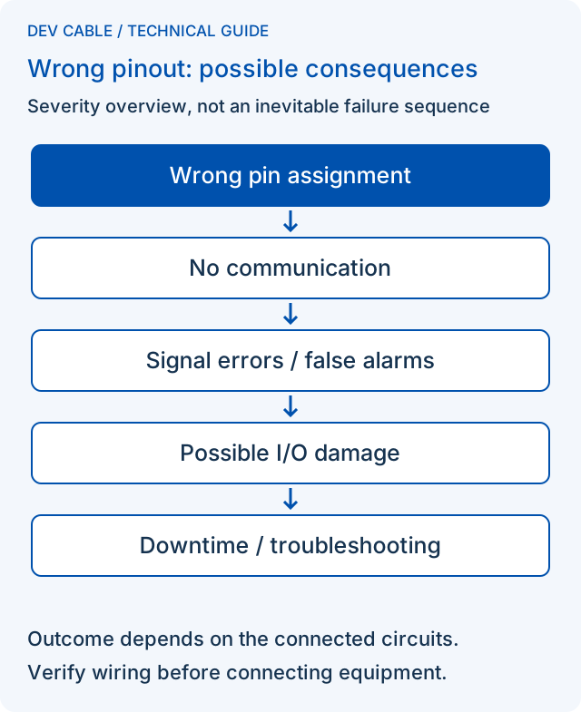
These are possible outcomes, not an inevitable chain of failures. The cable’s purchase price may be small compared with diagnostic labor, replacement boards and machine downtime. Verify the disconnected assembly against an approved map before connecting equipment.
Not Every D-Sub Pin Needs to Be Connected
An unused contact, a reserved position and a spare conductor are different things. Mark NC positions explicitly and describe how spare conductors are insulated and secured. Reserved contacts may need to remain untouched for equipment compatibility.
Signal ground, chassis ground, shield and duplicated return contacts may have different functions. Do not bridge them simply because they share a ground-related label. If several returns connect together, show the junction and conductor arrangement. The factory should never guess how unused positions should be treated.
Example Construction of a Shielded Monitoring Cable
The following educational example uses eight twisted pairs of 26 AWG stranded copper, an overall aluminum foil shield, a drain wire, tinned-copper braid and a PVC outer jacket.
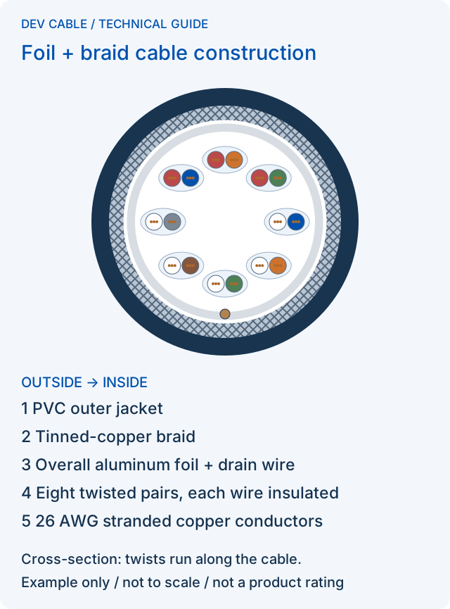
Example construction only. Actual conductor size, pair count, insulation, shielding and jacket depend on the application. The cross-section is schematic and not to scale.
An illustrative construction brief might specify 300 V cable insulation and braid coverage of at least 60%. These are example cable requirements, not ratings for all DEV CABLE products or an assembled D-Sub interface. Connector ratings, working current and the completed assembly still require confirmation.
Example pair colors are white/blue, white/orange, white/green, white/brown, white/grey, red/blue, red/orange and red/green. These identify eight physical pairs; they are not a universal color standard or signal map.
Eight pairs contain sixteen insulated conductors, so a 15-contact connector cannot give each conductor its own contact. Document unused conductors or approved shared connections without splitting a required signal pair. The drain and shield are additional to the sixteen insulated conductors.
Common Applications for Custom D-Sub Cable Assemblies
UPS Monitoring and Alarm Systems
Alarm outputs, status signals and shutdown control can share a D-Sub interface. Establish whether each circuit uses dry contacts, logic levels or serial communication; a generic serial cable may not match the UPS interface.
PLC and Industrial Automation
Digital I/O, serial communication and control circuits require distinct wiring definitions. Include signal returns, supply connections and cabinet grounding. Confirm the exact PLC module and interface revision.
Servo, Encoder and Motion Control
Feedback signals make physical pair assignment, polarity and shielding particularly important. Separate the feedback specification from motor-power cabling, and confirm movement, routing and permitted untwisted termination lengths with the equipment requirements.
CNC and Industrial Machinery
Proprietary machine interfaces can remain in service long after their original cable is discontinued. Match contact arrangement, locking screws, backshell clearance and exit direction as well as wiring.
Test and Measurement Equipment
Custom instrument I/O may combine triggers, analog channels and control signals. Record return paths and any leakage, capacitance or shielding requirements relevant to the measurement rather than assuming a general-purpose cable is adequate.
Telecom and Network Equipment
D-Sub connections can serve monitoring, alarms and control. Network equipment branding does not make every management connection Ethernet; confirm the actual interface before selecting an opposite-end connector.
Legacy Equipment Replacement
Discontinued, proprietary or undocumented assemblies can sometimes be reproduced from an original cable, clear connector photos, an equipment manual, a pinout table and continuity measurements. Record the equipment model and cable revision before comparing samples.
A damaged sample may contain the fault being investigated. Continuity alone cannot reveal all original pair, shield or active-component details. Feasibility review should resolve those uncertainties before a replacement drawing is approved; reverse engineering is not always possible.
How Custom D-Sub Cable Assemblies Should Be Tested
DEV CABLE performs 100% continuity testing on every finished cable assembly before shipment. The approved drawing should also establish the inspection scope and acceptance criteria:
- Pin-to-pin continuity: every intended circuit, including branches and returns, with an agreed resistance limit appropriate to length and gauge.
- Short-circuit and miswire checks: unintended connections, opens and incorrect destinations.
- Shield continuity: the specified shield path through the assembly.
- Shell verification: required shell bonds and intentional isolation at each end.
- Insulation resistance, where required: agreed circuits, limits and test conditions.
- Dielectric / HiPot testing, where required: approved voltage, duration and connection arrangement. Disconnect the cable from equipment; embedded components require a compatible test program, as explained in Cirris’ component-testing guidance.
- Functional testing, where agreed: representative equipment or a defined fixture and procedure.
- Visual inspection: contact seating, solder or crimp workmanship, markings and exposed conductors.
- Strain-relief inspection: cable retention and any agreed pull-test method and acceptance limit.
Confirm physical pair identity during manufacture; add electrical performance testing where specified. Additional tests and records should be agreed during quotation, rather than assumed from the word “tested.”
Continuity testing verifies wiring, but it does not by itself verify impedance, EMI performance or protocol compatibility.
What Should a D-Sub Wiring Drawing Include?
Give the drawing a part number and revision so purchasing, production and inspection use the same definition. Confirm the tester’s connection map independently against that drawing: a test learned only from a miswired sample can reproduce its error. Include:
- Ends: X1/X2 designation, connector part numbers, contact count, rows, gender, viewing direction and pin-numbering reference.
- Circuits: X1 pin → X2 pin, signal name, wire color, physical pair, conductor size and any branches.
- Grounding: shield, drain and shell connections, signal returns, NC contacts and spare-conductor treatment.
- Mechanics: finished length with measurement reference and tolerance, backshell, cable exit, screw type, strain relief and cable label.
- Notes: construction, environment, special requirements, tests and approval revision.
The following separate example shows a custom pair-preserving remap. It is not a production pinout:
| X1 | X2 | Function | Wire / group |
|---|---|---|---|
| 1 | 1 | A+ | White / pair 1 |
| 2 | 2 | A− | Blue / pair 1 |
| 3 | 6 | B+ | White / pair 2 |
| 4 | 7 | B− | Orange / pair 2 |
A released drawing must additionally define every remaining contact, spare wire and shield/shell connection. Define signal names from the equipment documentation, not inferred wire colors.
Information to Provide When Requesting a Quote
Use this RFQ checklist to avoid clarification delays:
- Connector A type, part number and gender.
- Connector B type, part number and gender.
- Complete pin assignment and viewing direction.
- Signal/protocol, voltage and current requirements.
- Finished cable length, tolerance and measurement points.
- Conductor size, core/pair count and physical pair mapping.
- Shield construction and termination at both ends.
- Jacket, temperature, oil/moisture exposure, bend radius and fixed or moving use; specify drag-chain or torsional duty where applicable.
- Prototype/production quantities and required delivery date; ask for MOQ, tooling charges and confirmed lead time.
- Required tests, acceptance limits and records.
- Labels, backshells, cable diameter, mating screw thread (for example, #4-40 UNC versus M3), clearance and packing requirements.
- Drawing revision or availability of a reference sample.
Without a formal drawing, send photos of both ends, equipment model, original cable, pin table, manual and continuity results. Resolve unknowns before production. For a new or reconstructed design, agree on first-article approval and record the approved sample/drawing revision before releasing the batch. The quotation turnaround is separate from manufacturing lead time.
Need a Custom D-Sub Cable?
Send the pin table and equipment details with your RFQ for DEV CABLE’s custom DB9, 15-pin D-Sub, DB25 or mixed-connector assemblies. Mark unresolved requirements so the quotation review can address them.
Explore D-Sub cable assembly options or send your RFQ through the enquiry form. A quotation is provided within 24 hours after receipt of a complete RFQ.