Custom D-Sub cable assemblies built around the equipment interface
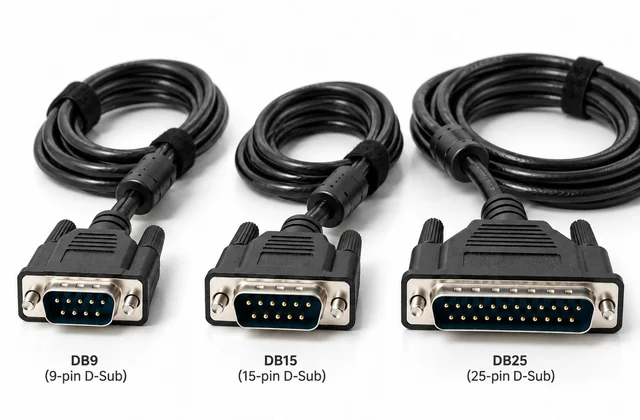
DEV CABLE supplies custom terminated assemblies based on drawings, pinout tables, approved samples or equipment interface requirements. This configurable product family, DEV-DSUB-CA, covers DB9 cable assembly, DB15 cable assembly and DB25 cable assembly enquiries, plus other D-Sub formats. Bare-wire ends are termination options within this family.
Typical enquiries include industrial control equipment, communication devices, test equipment, monitoring systems, automation equipment and console or management interfaces. Connector gender, contact count, pin assignment, conductor size, shielding, backshell, locking hardware and finished length all affect the completed assembly.
Why Choose Custom D-Sub Cable Assemblies – DB9, DB15, DB25 & Custom Terminations?
A D-Sub cable is more than a connector-to-connector link. Equipment can require its own pin assignment, conductor arrangement, shielding, connector gender and termination. The assembly should be specified against the actual electrical and mechanical interface rather than selected by contact count alone.
1. Pinouts matched to the equipment
Connectors with the same contact count can have different wiring. A customer pinout, wiring diagram or approved sample can define straight-through or crossed wiring, custom pin-to-pin mapping, connected and unused pins, shared or separate signal returns, and the grouping of power, signal and communication conductors. This is especially useful when replacing a proprietary or discontinued equipment cable. Confirm pin numbering and mating orientation before production.
2. DB9 for monitoring, serial links and control
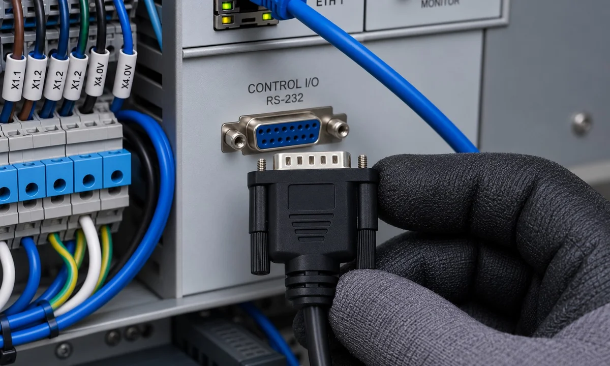
DB9 assemblies may be specified for UPS monitoring and alarms, RS-232 or RS-485 interfaces, PLCs and industrial controllers, machine diagnostics, programming ports or equipment control signals. Conductor size, twisted pairs, shielding and pinout must follow the actual interface. A DB9 connector by itself does not establish the communication protocol or compatibility.
3. DB15 for motion control and feedback
DB15 assemblies can carry servo-drive, encoder, motion-control and machinery signals, including feedback, control, alarms and auxiliary power where the equipment design calls for them. Twisted pairs, separate power and signal conductors, and overall or individual shielding can be reviewed to manage interference near motors and power cables. Confirm whether the mating connector is a two-row 15-pin D-Sub / DA-15 or a three-row HD15 / DE-15; they are not interchangeable.
4. DB25 for multiple control and I/O signals
DB25 offers more contacts for project-defined control, communication or I/O wiring in automation, CNC machinery, test and measurement, data acquisition, multi-channel control and legacy industrial equipment. Specify conductor size, shield arrangement and internal grouping against the actual signal map instead of assuming a generic 25-core cable will fit.
5. Cable construction selected for the environment
Options for engineering review include conductor AWG and count, PVC or PUR jacket requirements, flexible construction for moving equipment, twisted pairs, foil or braid overall shielding, individual pair shields, drain wires, grounding, diameter and length. Where motors or inverters create interference, the shield and termination scheme must be reviewed with the equipment grounding design; shielding alone does not guarantee EMC performance.
6. Connector and termination options for OEM projects
The second end can be bare wire, a terminal block or a project-specified industrial connector instead of another D-Sub. Male-to-male, male-to-female and female-to-female layouts, molded ends, metal or plastic hoods, and #4-40 UNC locking hardware can be reviewed against the mating interface and quantity. These choices support OEM machinery, replacement cables and small industrial projects when an off-the-shelf cable does not match the required wiring or construction.
Built around your pinout and application
For a useful RFQ, provide the pinout, signal types, conductor size, shielding and grounding requirements, length, connector gender and operating environment. DEV CABLE can review a drawing, wiring table, equipment specification or existing sample for prototype and production requirements. Final materials, terminations and tests are confirmed for the approved assembly.
D-Sub cable assembly configuration
| Component | RFQ information |
|---|---|
| Connector A | DB9, DB15 / 15-pin D-Sub, DB25 or another specified D-Sub connector |
| Gender | Male or female at both ends; confirm pin numbering |
| Connector B | D-Sub, bare wire / flying leads, crimp terminals, RJ45, USB, circular or project-specified connector, subject to engineering review |
| Pinout | Standard, point-to-point, crossed or customer-defined wiring; provide a drawing or wiring table |
| Cable | AWG, core/pair count, conductor construction, insulation and jacket |
| Shielding | Unshielded, foil, braid or foil + braid |
| Backshell | Plastic, metallized, metal or project-specified type |
| Locking hardware | Screws and mating hardware according to the equipment interface |
| Mechanical details | Finished length, bend/exit direction, strain relief and handling requirements |
| Identification | Cable printing, heat-shrink markers, labels or serialized identification if required |
| Testing | Continuity, pin-to-pin verification and additional project-specific requirements |
| Quantity | Prototype, trial batch or production quantity; specify packing |
Typical shielded signal cable construction
A reference construction may use 26AWG stranded copper, 2 / 4 / 6 / 8 / 13 twisted pairs for selected constructions, HDPE insulation, aluminum foil plus tinned-copper braid, a tinned-copper drain wire and a PVC jacket. These are customizable examples; conductor size, pair count, shielding and jacket are selected for the application, not fixed family specifications.
Voltage, current, temperature range, impedance and environmental requirements must be confirmed for the chosen cable and completed assembly. A connector shape or shielding option does not establish a protocol, EMC rating or equipment compatibility. An RJ45 or USB termination does not by itself provide Ethernet/USB functionality or active protocol conversion.
Quality control and configuration approval
Completed assemblies are checked against the approved wiring definition before shipment. 100% continuity testing is performed on every finished cable assembly before shipment. Define additional insulation-resistance, dielectric, shielding, dimensional or functional tests during RFQ review.
Required standards, certifications, marking and approval documents are reviewed for the exact configuration. This family page does not establish blanket certification. Prototype, small-batch and production supply are subject to RFQ review.
How to request a quotation
Provide connector type and gender at both ends, pinout or wiring table, AWG, core/pair count, cable construction, shielding, jacket, finished length, backshell, locking details, marking, quantity, packing and required testing or documentation. If a part number is unknown, send a clear drawing, photograph, equipment interface specification or existing sample for engineering review.
A technical quotation is provided within 24 hours after receiving a complete RFQ.
Frequently asked questions
Can you make custom DB9, DB15 and DB25 pinouts?
Yes. Pin assignments can follow customer wiring tables, drawings or approved samples. Connector gender and pin numbering must be confirmed before production.
Can one end be bare wire or another connector?
Yes. Bare wire, crimp terminals, another D-Sub or a project-specified connector can be reviewed as the second end. Engineering review determines feasibility; this does not create a separate SKU.
What information is needed for a custom D-Sub cable?
Specify connector type, gender, pinout, cable construction, shielding, length, quantity and testing. Include hardware, marking and documentation requirements so the complete assembly can be reviewed.
Are DB15 and HD15 the same connector?
No. “DB15” is often used for different 15-pin D-Sub formats. A two-row 15-pin D-Sub / DA-15 and a three-row HD15 / DE-15 / VGA connector are mechanically different and are not interchangeable. Confirm the layout and mating interface by drawing, part number or photo.
Can you manufacture from an existing sample?
A sample, drawing, connector part number or wiring table can support engineering review. Final production requirements must be confirmed before manufacture.
What is the difference between solid and hollow contacts?
Gold-plated solid contacts are precision-machined from solid stock; gold-plated hollow contacts are stamped and formed from sheet metal. Machined contacts are typically selected for greater mechanical robustness and may offer higher current ratings in comparable D-Sub families, while stamped-and-formed contacts reduce weight and cost for commercial-volume assemblies. Exact current, wire range, mating-cycle and reliability ratings come from the selected connector part number—not from “solid” or “hollow” alone.
What is the difference between gold, tin and nickel contact finishes?
Gold resists oxidation and is generally preferred for low-level signals, repeated mating or humid/corrosive service. Tin is lower-cost and often suits lower-cycle general-purpose connections but is more susceptible to oxide and fretting-related resistance changes. Nickel is commonly the underplate beneath gold or tin, providing a diffusion and wear barrier; an exposed nickel mating finish must be evaluated as its own contact system. Confirm the mating pair, finish system and thickness, signal/current level, mating cycles and environment; do not mix finishes unless the connector manufacturer approves the combination.