A thermocouple measures temperature through a small voltage. The cable between the probe and the instrument is part of that measurement circuit. The wrong conductor alloys, reversed polarity or a hot transition point can shift a reading even when every wire passes a continuity check. A useful purchase specification covers both measurement accuracy and the conditions along the cable route.
Consider an anonymized, illustrative RFQ for a Type K installation. The buyer asks for two pairs (four insulated conductors), 20 AWG stranded conductors, PFA core insulation, a stainless steel overbraid and a cable operating range of 0–200°C. The description gives the factory a starting point. To quote a buildable design, it still needs the extension grade, tolerance class, identification scheme and location of the hot spots and terminations.
What Is K-Type Thermocouple Extension Cable?
A Type K thermocouple joins two dissimilar nickel alloys at its measuring tip. Its positive leg is nickel-chromium (commonly known as Chromel) and its negative leg is nickel-aluminium (commonly known as Alumel). The circuit produces a voltage related to the temperatures of the measuring and reference junctions. A compatible input uses cold-junction compensation at its terminals to determine the measuring-junction temperature. NIST thermocouple reference tables
Thermocouple-grade wire is used to form the sensing junction and is specified for the probe’s measurement duty. KX extension-grade wire uses the same nominal alloy compositions as Type K and carries its signal over a defined extension-wire temperature range. KC compensating wire uses different alloys to approximate the Type K voltage–temperature relationship over a specified range. Under IEC 60584-3:2021, KCA and KCB are distinct compensating types, so an order that says only “KC” needs clarification. IEC 60584-3:2021
Ordinary copper instrumentation cable cannot replace the extension pair in a run to a thermocouple input. The transition to copper moves the reference junction to that connection. A temperature difference between the transition and the instrument’s cold-junction sensor can then cause error. Copper wiring can be appropriate downstream of a field transmitter that already measures and compensates the thermocouple signal. Confirm the alloy composition of both legs, polarity at both ends and the required thermoelectric tolerance before approving a KX specification.
Understanding a 2-Pair 20 AWG Thermocouple Cable
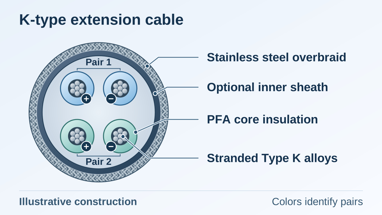
Two pairs mean four insulated signal conductors. Each pair contains one positive and one negative leg for a single Type K measurement channel. Specify a durable pair identifier and polarity marking that technicians can recognize at both ends, even after stripping back a jacket or sheath. Give the applicable colour-coding system and edition because IEC and ANSI colours differ. A core count alone leaves the pairing open, and a drain wire does not count as a signal core.
Specify 20 AWG per conductor and confirm the strand count, strand diameter and finished conductor size against the selected terminals. Stranded wire is generally easier to handle on routes with bends or vibration. A solid conductor can be practical for a fixed installation where the terminals accept it. For a long run, check the proposed loop resistance against the instrument input requirements. Gauge alone does not establish the resistance of a nickel-alloy pair.
The table describes an illustrative RFQ. The exact combination requires engineering confirmation before it can be offered for a project.
| Parameter | Example requirement |
|---|---|
| Thermocouple type | Type K |
| Extension grade | KX, subject to confirmation |
| Pair count | 2 pairs |
| Total cores | 4 insulated signal conductors |
| Conductor alloys | Nickel-chromium (+) and nickel-aluminium (−), exact compositions to confirm |
| Conductor construction | Stranded |
| Conductor gauge | 20 AWG per conductor |
| Core insulation | PFA |
| Outer mechanical protection | Stainless steel overbraid |
| Requested cable temperature range | 0–200°C, continuous duty to be confirmed |
The hero illustration shows this layout schematically. The inner sheath is optional, and its inclusion and material depend on the approved design.
Why Choose PFA Insulation for Thermocouple Extension Cable?
PFA is a melt-processable fluoropolymer that can be extruded around individual conductors. Its heat resistance, dielectric properties, low moisture uptake and chemical resistance make it a candidate for process routes exposed to heat, damp conditions or chemicals. Identify the chemicals, concentrations, exposure duration and cleaning conditions when selecting insulation. Water can still enter at an unsealed connector or cable end, and the jacket or braid may need a separate chemical compatibility review. Chemours PFA resin data
FEP is also melt-processable and can be suitable where the thermal demand is lower. PTFE offers a high-temperature option and uses different processing methods from conventional melt extrusion. PFA can be useful when the design calls for extrusion and greater thermal margin than the proposed FEP construction provides. The actual selection depends on the resin grade, insulation wall thickness, cable construction, continuous duty conditions and the ratings of the complete cable assembly. For a closer look at two of these material families, see the FEP and PFA cable insulation guide.
Stainless Steel Overbraid vs Electrical Shielding
In this example the stainless steel overbraid is the outer mechanical layer. It can improve abrasion resistance, protect the underlying cable from contact with rough surfaces or external damage, and reinforce the bundle. Specify the required mechanical duty, including how the braid is retained and where the cable is supported. A metallic appearance alone tells the buyer little about electrical screening performance. OMERIN Thermocouple & RTD Sensor Cable Technical Catalogue
| Construction | Primary role | What to specify |
|---|---|---|
| Stainless steel overbraid | Abrasion protection and mechanical reinforcement | Mechanical duty, braid construction and end restraint |
| Tinned copper braid | Conductive EMI screen with a robust termination path | Coverage, individual or overall screen, and how to bond the braid at each end |
| Aluminium foil with drain wire | High-coverage EMI screen around a pair or cable bundle | Foil overlap, drain contact and how to terminate or isolate each screen |
A tinned copper braid can be clamped to compatible conductive termination hardware. Its coverage depends on the weave. An aluminium foil screen can cover more of the circumference with little added bulk, while a drain wire provides a practical electrical connection. The drain carries the shield connection and should stay separate from the thermocouple signal circuit. Foil overlap, flexing duty and termination details affect screening performance.
If the cable will run near variable-frequency drives, switching equipment or motor feeders, specify a dedicated electrical shield inside the mechanical overbraid as needed. Individual pair shields can help manage coupling between channels. An overall shield addresses noise coupled from outside the bundle. Define where each screen and the overbraid are bonded or isolated, using the instrument manufacturer’s grounding instructions and the plant’s EMC design. Include those details on the termination drawing so the installer can preserve the intended isolation and continuity.
What Does a 200°C Cable Requirement Mean?
Check three temperature limits independently:
- Measuring junction. The probe tip must be suitable for the process temperature, taking its sheath and installation into account.
- Extension-wire tolerance. The conductor grade and class define the allowable deviation from the reference thermoelectric response over a stated temperature interval. IEC 60584-3:2021 gives a −25°C to +200°C tolerance validity range for KX. Specify the applicable class and edition. This interval describes thermoelectric tolerance.
- Cable operating temperature. The insulation, any inner sheath or jacket, and other components must withstand the specified exposure in the actual assembly. Obtain the continuous operating range for the proposed construction. Separate short heat excursions and installation temperatures from the continuous requirement.
For example, a probe may measure from 0–600°C while the extension cable is requested for 0–200°C and the mating connector for 0–100°C. The probe tip can enter the process while its head and connector sit outside the hot zone. Verify the expected temperatures at the head, connector and along the entire cable route, including hot spots from radiant heat. If the plug could reach 120°C, relocate it to a cooler point or select a connector with a suitable rating. PFA insulation by itself cannot establish continuous service at 200°C for the assembled cable.
How to Specify a Custom K-Type Thermocouple Extension Cable
Use this checklist to make competing quotes comparable. Where the supplier is expected to propose a solution, state the operating requirement and identify what needs approval on the drawing.
| RFQ item | Detail to provide or confirm |
|---|---|
| 1. Thermocouple type | K, J, T, E or the type specified by the instrument and probe. |
| 2. Cable grade | Extension grade or the exact compensating grade. |
| 3. Conductor alloys | Nominal alloy composition and polarity for each leg. |
| 4. Tolerance class | Applicable standard and edition, class and required validity range. |
| 5. Pair and core count | Number of circuits and total insulated signal conductors. |
| 6. Conductor gauge | AWG or cross-sectional area per conductor. |
| 7. Conductor construction | Solid or stranded, with strand construction or terminal constraints. |
| 8. Core insulation | PFA, FEP or PTFE, plus any specified insulation wall or dielectric requirement. |
| 9. Identification | Colour-coding system, pair numbering, polarity and cable markings. |
| 10. Electrical shield | Individual or overall screen, material, drain and termination arrangement. |
| 11. Mechanical protection | Stainless steel overbraid or other protection and the expected mechanical exposure. |
| 12. Inner sheath and outer jacket | Required materials, outside diameter limits and chemical or moisture exposure. |
| 13. Operating temperature | Continuous range, hot spots, excursions and installation conditions. |
| 14. Length and packaging | Total quantity, cut length or length per reel and reel markings. |
| 15. Tests and documents | Drawing approval, test methods, acceptance criteria and required reports. |
When the RFQ includes probes or plugs
For each probe, confirm insertion length, sheath dimensions, process connection and the measuring-junction range. For each plug or socket, specify connector size, male or female gender, mating part, thermocouple contact type, polarity, cable entry and local temperature rating. Confirm where the probe, cable and connectors transition between temperature zones. A termination drawing can identify each mating interface and the intended channel assignment.
Industrial Applications
- Petrochemical plants and refineries use thermocouple circuits between field sensor heads and monitoring equipment. Check radiant heat along the route and exposure to oils or cleaning agents.
- Power generation uses thermocouple inputs for temperature monitoring around boilers and auxiliary equipment. Keep measurement wiring clear of high-noise power routes where practical.
- Steel, metallurgy and heat-treatment furnaces often require a cooler transition point outside the hot enclosure and mechanical protection where cable passes equipment or supports.
- Chemical processing calls for checking each exposed layer against the actual splash or washdown environment, including the connector and its seal.
- Process automation and temperature control can use multipair cable to bring several channels to a transmitter panel or PLC input module. Identify pairs by loop or channel so technicians can trace them during commissioning.
Why Choose DEV CABLE for Custom Thermocouple Extension Cable?
DEV CABLE is a custom industrial cable manufacturer in China. Its shielded thermocouple extension cable range includes factory-listed Type K, T, J and E models and covers several insulation families. Project reviews can address single- or multi-pair layouts, solid or stranded conductors, conductor gauge, finished dimensions, electrical shielding and mechanical protection. Ask about minimum order quantities for the proposed build, including small-batch options, and provide your drawings and specifications for review.
Requests for PFA, FEP or PTFE, including a PFA-insulated design with stainless steel overbraid, are reviewed as project-specific constructions. Engineering confirmation covers alloy grade, material compatibility, dimensions and operating limits. DEV CABLE performs 100% continuity testing before shipment. Agree separately on any thermoelectric tolerance verification, insulation tests or documentation needed for acceptance.