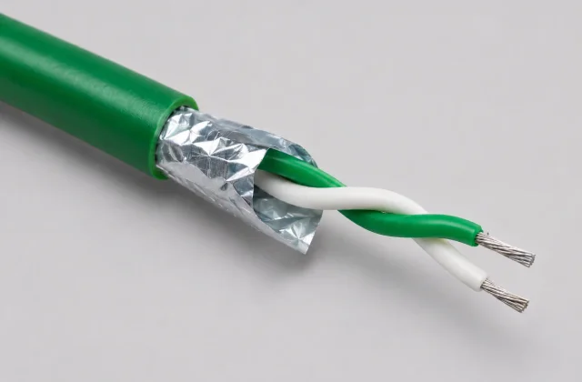

A shielded thermocouple extension cable connects a compatible thermocouple sensor circuit to temperature measurement instruments, transmitters, PLC thermocouple inputs and industrial control equipment. Maintaining the required thermoelectric characteristics depends on the approved conductor alloys, grade, tolerance and application temperature range.
DEV CABLE manufactures custom industrial cables around project requirements. The factory model matrix below lists Type K, T, J and E thermocouple wires and cables. These type labels do not, by themselves, verify extension or compensating grade. Confirm the selected model’s alloy composition and thermoelectric tolerance before specifying it as extension cable. Other thermocouple types and special constructions can be discussed subject to factory engineering confirmation.
Correct alloy selection and polarity support measurement accuracy. Shielding helps manage electrical interference, while insulation and sheath selection address the installation environment. These are separate selection decisions: a suitable jacket cannot correct the wrong conductor alloy, and a shield does not establish thermoelectric accuracy.
For ordinary equipment or instrumentation signals, compare MVVS shielded signal cable. For fixed industrial control circuits, review CVV-S shielded PVC control cable and the Industrial Cables Catalog. Their copper conductors, shielding or ratings do not establish suitability as thermocouple extension wire.
Thermocouple Types and Conductor Materials
The following table gives nominal thermocouple material pairings and IEC identification conventions for the four types listed in the factory matrix. It is a selection reference, not verification of an individual factory model’s alloy composition, extension grade or tolerance.
| Thermocouple Type | Positive Conductor (+) | Negative Conductor (-) | IEC Outer Sheath Colour |
|---|---|---|---|
| K | Nickel-Chromium (NiCr / Chromel) | Nickel-Aluminium (NiAl / Alumel) | Green |
| J | Iron (Fe) | Copper-Nickel (CuNi / Constantan) | Black |
| T | Copper (Cu) | Copper-Nickel (CuNi / Constantan) | Brown |
| E | Nickel-Chromium (NiCr) | Copper-Nickel (CuNi / Constantan) | Violet |
For these IEC types, the positive conductor insulation follows the listed sheath colour and the negative conductor insulation is white. ANSI colour identification is different and can be specified for the project. Do not combine IEC and ANSI colours within one identification scheme or infer polarity from a colour without first identifying the standard.
Technical note: Final conductor materials and identification shall follow the customer’s specified standard and approved product construction. Alloy names identify material families; the required thermoelectric tolerance must also be specified. RECKMANN’s technical guide explains extension-wire identification and the distinction between conductor application limits and insulation limits.
Extension cable and compensating cable grades are not interchangeable. Extension conductors nominally correspond to the associated thermocouple materials; compensating conductors use different materials to reproduce the required thermoelectric behaviour over a specified, limited range. A factory model’s Type K, T, J or E label is not sufficient evidence of either grade.
Shielded Thermocouple Extension Cable — Available Constructions
These options form a starting point for a custom enquiry, based on established industry constructions and the requested design scope. They are not a stock list or a claim that every combination is already validated. Confirm material compatibility, manufacturing feasibility and the final specification during technical review.
| Parameter | Available Options |
|---|---|
| Thermocouple Type | Factory-listed K, T, J and E; other types subject to engineering confirmation |
| Cable Construction | Single pair / multi-pair |
| Conductor Material | Type-specific materials; exact alloy, grade and thermoelectric tolerance require model-specific confirmation |
| Conductor Construction | Solid / stranded |
| Conductor Size | 20 AWG, 18 AWG, 16 AWG; 0.22, 0.5, 0.75, 1.0, 1.5 mm² and customized sizes, subject to design confirmation |
| Core Insulation | Factory-listed TT Teflon, GG glass fiber, HH high-temperature glass fiber and XS ceramic fiber; other materials such as PVC, HRPVC, PE, XLPE, FEP, PTFE, PFA or silicone rubber require custom design review |
| Pair Identification | IEC or ANSI colour coding, as separately specified; multi-pair circuit identification agreed for the design |
| Shielding | P-XS-K-20-SLE is factory-identified as shielded. Overall/individual/combined foil or tinned copper braid are separate custom options, not verified for all listed models |
| Drain Wire | Bare or tinned copper, as specified for the shield construction |
| Inner Sheath | PVC, PE, XLPE or customized material |
| Armouring | Optional steel wire braid or other engineered mechanical protection |
| Outer Sheath | PVC, HRPVC, LSZH, FEP, PFA or customized material |
| Temperature Rating | According to the extension conductor type and selected insulation/sheath system; final limits require confirmation |
| Voltage Rating | Project-specific; confirm for the final cable construction |
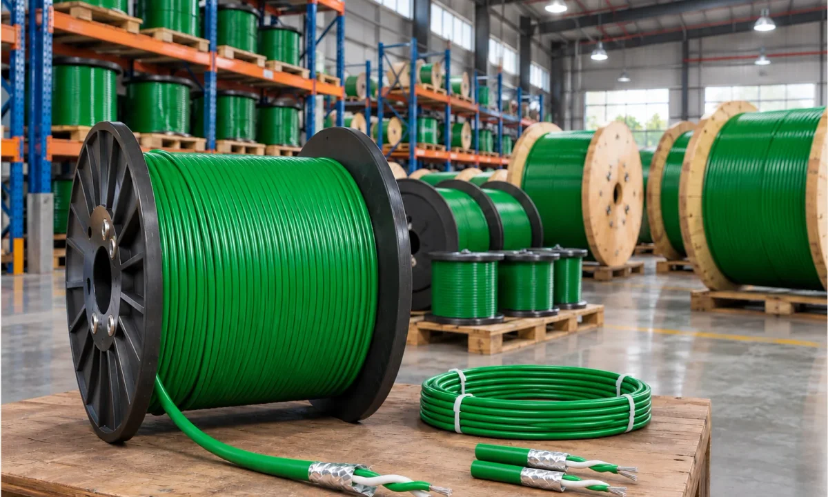
| Packaging | Coils / reels / wooden drums; lengths and packing agreed for the order |
| Customization | According to customer drawings and technical requirements, subject to engineering confirmation |
AWG and mm² sizes above are independent custom-enquiry options, not conversions of the factory conductor notation below. The detailed model tables provide the factory’s two overall dimensions; their orientation and tolerances still require confirmation. Other dimensions, insulation thickness, weight per kilometre, electrical ratings, mechanical properties and tolerances are available upon technical confirmation or quotation. No universal voltage or operating-temperature rating is assigned to this family.
Detailed Technical Specifications & Model Selection
DEV CABLE manufactures thermocouple wires and cables in a range of insulation systems, thermocouple types and conductor sizes, from fine-wire constructions to high-temperature glass fiber and ceramic fiber designs.
The following 28 model specifications reproduce the current factory-provided technical data. Additional conductor sizes, cable dimensions and special constructions can be developed according to project requirements, subject to engineering review. The type labels and temperature figures are retained as supplied; the Technical Notes below explain the grade, temperature and shielding confirmations needed for selection.
Teflon-Insulated Thermocouple Extension Cable (TT Series)
The TT series uses a Teflon Insulated / fluoropolymer system and includes Type K, T, J and E constructions for applications requiring compact conductor configurations. The factory identifies the material family as Teflon; the specific PTFE, FEP or PFA resin grade is not confirmed.
| Thermocouple Type | Factory Model | Conductor Construction / Diameter | Overall Dimensions (mm) | Factory-Stated Temperature Range (°C) |
|---|---|---|---|---|
| K | TT-K-44-SLE |
2 × 0.05 mm | 0.2 × 0.35 | -40 to 260°C |
| K | TT-K-40-SLE |
2 × 0.08 mm | 0.35 × 0.65 | -40 to 260°C |
| K | TT-K-36-SLE |
2 × 0.127 mm | 0.5 × 0.8 | -40 to 260°C |
| K | TT-K-30-SLE |
2 × 0.255 mm | 0.6 × 1.0 | -40 to 260°C |
| K | TT-K-24-SLE |
2 × 0.51 mm | 1.4 × 2.4 | -40 to 260°C |
| K | TT-K-24S-SLE |
2 × 7 × 0.2 mm (Stranded) | 1.6 × 2.6 | -40 to 260°C |
| K | TT-K-20-SLE |
2 × 0.8 mm | 1.7 × 3.0 | -40 to 260°C |
| T | TT-T-36-SLE |
2 × 0.127 mm | 0.5 × 0.8 | -200 to 260°C |
| T | TT-T-30-SLE |
2 × 0.255 mm | 0.6 × 1.0 | -200 to 260°C |
| T | TT-T-24-SLE |
2 × 0.51 mm | 1.4 × 2.4 | -200 to 260°C |
| T | TT-T-20-SLE |
2 × 0.8 mm | 1.7 × 3.0 | -200 to 260°C |
| J | TT-J-36-SLE |
2 × 0.127 mm | 0.5 × 0.8 | -40 to 260°C |
| J | TT-J-30-SLE |
2 × 0.255 mm | 0.6 × 1.0 | -40 to 260°C |
| J | TT-J-24-SLE |
2 × 0.51 mm | 1.4 × 2.4 | -40 to 260°C |
| J | TT-J-20-SLE |
2 × 0.8 mm | 1.7 × 3.0 | -40 to 260°C |
| E | TT-E-30-SLE |
2 × 0.255 mm | 0.6 × 1.0 | -40 to 260°C |
| E | TT-E-24-SLE |
2 × 0.51 mm | 1.4 × 2.4 | -40 to 260°C |
Glass Fiber Insulated Thermocouple Extension Cable (GG Series)
The GG series uses glass fiber insulation and includes Type K and Type T constructions for applications requiring higher temperature resistance than conventional polymer-insulated designs. The factory states different ranges for the two Type T models; use each row’s value and confirm its application basis before selection.
| Thermocouple Type | Factory Model | Conductor Construction / Diameter | Overall Dimensions (mm) | Factory-Stated Temperature Range (°C) |
|---|---|---|---|---|
| K | GG-K-36-SLE |
2 × 0.127 mm | 0.8 × 1.1 | -40 to 480°C |
| K | GG-K-30-SLE |
2 × 0.255 mm | 0.9 × 1.3 | -40 to 480°C |
| K | GG-K-24-SLE |
2 × 0.51 mm | 1.4 × 2.4 | -40 to 480°C |
| K | GG-K-24S-SLE |
2 × 7 × 0.2 mm (Stranded) | 1.6 × 2.6 | -40 to 480°C |
| K | GG-K-20-SLE |
2 × 0.8 mm | 1.7 × 3.0 | -40 to 480°C |
| T | GG-T-36-SLE |
2 × 0.127 mm | 0.8 × 1.1 | -40 to 480°C |
| T | GG-T-30-SLE |
2 × 0.255 mm | 0.9 × 1.3 | -40 to 260°C |
High-Temperature Glass Fiber Thermocouple Cable (HH Series)
The HH series provides high-temperature glass fiber insulation constructions for demanding industrial temperature measurement applications. The P-HH model prefix is preserved as supplied; it does not establish a particular shield material or construction.
| Thermocouple Type | Factory Model | Conductor Construction / Diameter | Overall Dimensions (mm) | Factory-Stated Temperature Range (°C) |
|---|---|---|---|---|
| K | HH-K-24-SLE |
2 × 0.51 mm | 1.4 × 2.3 | -40 to 704°C |
| K | P-HH-K-24-SLE |
2 × 0.51 mm | 2.1 × 2.9 | -40 to 704°C |
Ceramic Fiber High-Temperature Thermocouple Cable (XS Series)
The XS series uses the factory-described ceramic fiber insulation for specialized high-temperature measurement environments where conventional polymer insulation is unsuitable. The figures below are the factory-stated model ranges; they are not a universal rating for every ceramic fiber cable.
| Thermocouple Type | Factory Model | Conductor Construction / Diameter | Overall Dimensions (mm) | Factory-Stated Temperature Range (°C) |
|---|---|---|---|---|
| K | XS-K-20-SLE |
2 × 0.8 mm | 1.9 × 3.0 | 0 to 1000°C |
| K | P-XS-K-20-SLE |
2 × 0.8 mm | 3.0 × 4.6 | 0 to 1000°C |
Factory-identified shielded model:
P-XS-K-20-SLE— 1000°C High-Temperature Shielded Wire. The factory explicitly identifies this model as shielded. Confirm shield material, construction and the temperature basis for the intended duty. The other XS model is not assumed to be shielded.
Technical Notes
- All model numbers, conductor notation and overall dimensions above are based on the factory-provided specifications.
- Overall dimensions retain the factory’s two-dimension format. Confirm width/thickness orientation and tolerances before issuing a detailed engineering drawing.
- Temperatures are factory-stated ranges. Confirm whether each describes continuous cable operating temperature, insulation service limits or measurement application ranges; they do not by themselves verify thermoelectric accuracy throughout that range.
- Confirm the exact conductor alloy composition, applicable thermocouple/extension/compensating grade and thermoelectric tolerance against the approved model specification.
- Special conductor sizes, stranded constructions and customized cable dimensions are available subject to engineering review. The tables do not validate every possible material or size combination.
- Specify shielding separately where applicable. A model prefix alone does not establish foil, braid, drain wire or shield material.
- The factory explicitly identifies
P-XS-K-20-SLEas a high-temperature shielded wire. This does not make all 28 models shielded. - Confirm the TT family resin grade before labeling an individual model PTFE, FEP or PFA.
- The supplied matrix does not establish a voltage rating, flame-retardant classification, international approval or blanket IEC/ASTM compliance.
How to Select the Right Thermocouple Cable
By Insulation Family
| Series | Insulation Family | Factory-Stated Temperature Range |
|---|---|---|
| TT | Teflon / Fluoropolymer | Up to 260°C |
| GG | Glass Fiber | Up to 480°C |
| HH | High-Temperature Glass Fiber | Up to 704°C |
| XS | Ceramic Fiber | Up to 1000°C |
These summaries describe the supplied model ranges, not universal operating ratings for every construction. Use the full lower and upper values for the selected model, including the GG Type T exception, and confirm what the factory’s temperature figures represent.
By Thermocouple Type
- Type K: TT, GG, HH and XS series.
- Type T: TT and GG series.
- Type J: TT series.
- Type E: TT series.
Other thermocouple types and special constructions may be discussed on a project-specific basis, subject to factory engineering confirmation. Confirm alloy composition, grade, tolerance and identification for the selected model; the type label alone does not establish extension-grade suitability.
By Conductor Construction
- 2 × 0.51 mm: two conductor cores with the factory-specified 0.51 mm conductor dimension.
- 2 × 7 × 0.2 mm: two conductors, each specified as seven strands of 0.2 mm diameter.
The original factory notation is retained in every row. These dimensions have not been converted to AWG or mm². Confirm any requested conversion and the required conductor construction with the factory before ordering.
Construction and Shielding Selection
Conductor pair and identification
Choose the extension type to match the thermocouple sensor and instrument configuration. Specify the thermoelectric tolerance requirement, conductor size and solid or stranded construction. In a multi-pair thermocouple cable, identify each circuit while retaining the required polarity identification. Confirm terminal suitability and circuit resistance with the measurement equipment requirements.
Foil shielding, braid and drain wire
An overall aluminium-polyester foil shield with a drain wire provides a practical shielding and termination arrangement around the assembled pair or pairs. Individual pair shields separate circuit shielding; combined individual and overall foil shielding adds an outer shield around the cable assembly. Specify how individual screens remain isolated or are bonded at the termination.
A tinned copper braided shield is another construction option. Foil and braid differ in coverage, resistance, mechanical behaviour and termination method; neither is universally best for every interference source. Define the shield arrangement with the equipment’s bonding instructions, cable routing and noise environment. Shielding helps reduce electromagnetic interference but does not guarantee a noise-free measurement circuit.
The drain wire serves the shield connection; it is not a thermocouple signal conductor. Steel wire braid or other armouring provides specified mechanical protection and should not automatically be treated as an equivalent signal shield. The green-jacket product illustration shows foil and two insulated cores; it does not document a separate drain wire or establish the final ordered construction.
Insulation, inner sheath and outer jacket
The detailed factory matrix identifies TT Teflon, GG glass fiber, HH high-temperature glass fiber and XS ceramic fiber insulation. It does not identify the TT resin as PTFE, FEP or PFA. PVC, heat-resistant PVC, PE, XLPE, FEP, PTFE, PFA and silicone rubber can be discussed as separate custom-material requirements, subject to engineering review. An inner sheath and outer jacket must be selected for the approved construction; materials are not interchangeable or available in every model combination.
Identify ambient heat, moisture, oils, chemicals, cleaning exposure, abrasion and movement before choosing the material system. Fiberglass insulation alone does not establish a moisture-tight cable. A requested LSZH sheath does not, by itself, establish a tested flame, smoke or halogen classification. Confirm any required performance and supporting evidence for the complete construction.
Industrial Temperature Measurement Applications
- Petrochemical and refinery temperature monitoring: connect suitable sensor circuits to measurement and control equipment.
- Power generation and energy plants: extend temperature measurement circuits along an appropriately specified route.
- Industrial process automation: link thermocouples to transmitters or PLC thermocouple input modules.
- Steel and metallurgy production: route extension wiring away from excessive radiant heat and mechanical damage.
- Furnace and heat-treatment equipment: select the cable for the connection-point and cable-route temperatures, separately from furnace temperature.
- Plastic and rubber processing machinery: specify measurement wiring around heaters, moulds and process equipment.
- Food and pharmaceutical manufacturing: assess cleaning chemicals, moisture and installation conditions; sector use alone does not establish hygienic or food-contact approval.
- Industrial instrumentation and control systems: organize single or multiple thermocouple circuits between field equipment and control cabinets.
Select insulation and installation location for ambient temperature, exposure and the confirmed limits of the complete cable.
Temperature Limits and Standards
The sensor’s measuring-junction temperature, the extension conductor’s thermoelectric application range, and the insulation/sheath temperature resistance are different limits. A high-temperature insulation material does not expand the temperature range over which an extension alloy meets its specified tolerance. The actual cable rating must respect both the applicable conductor type and the complete insulation/sheath system, including the installation conditions.
Keep the extension connection and cable route within their approved limits, especially near furnaces or heat-treatment equipment. Specify connection-point, ambient, operating and installation temperatures rather than using process temperature as the cable rating.
IEC 60584-3 addresses thermocouple extension and compensating cable tolerances and identification. ASTM E230/E230M provides thermocouple temperature–electromotive-force reference tables and related tolerance and identification specifications. State the required standard, edition, tolerance and identification system in the RFQ; a reference to one does not establish compliance with the other.
Custom constructions are reviewed with reference to applicable thermocouple extension cable requirements. Specific thermoelectric tolerance, material selection and testing must be agreed for the project. This page makes no blanket conformity claim and does not claim UL, CSA, ATEX or other product approvals. Hazardous-area installation requires a separate review of the exact cable, equipment and applicable project requirements.
Need a Custom Thermocouple Extension Cable?
Tell us your thermocouple type, conductor size, pair count, shielding requirements and operating environment. DEV CABLE can work with your technical specifications to develop a suitable cable construction. Include:
- Factory model code and thermocouple type: K, T, J or E from the matrix, or a separately reviewed custom requirement.
- Reference standard and edition, thermoelectric tolerance, and IEC or ANSI identification.
- Number of pairs and any circuit numbering or identification requirements.
- Conductor size in AWG or mm² and solid or stranded construction.
- Overall, individual or combined shielding, drain-wire requirements and termination arrangement.
- Core insulation, inner sheath, outer jacket, colour and marking requirements.
- Armouring or other mechanical protection, if needed.
- Required length per coil, reel or drum, total quantity and packaging.
- Operating, ambient, connection-point and installation temperatures.
- Installation location, moisture, chemicals, movement and other exposure conditions.
- Required electrical ratings, drawings, tests, acceptance documents and destination.
Every finished cable length undergoes 100% continuity testing before shipment. Thermoelectric accuracy, insulation resistance, dielectric testing or other project-specific checks must be defined separately in the agreed specification; continuity testing alone does not establish those properties.
Use the quotation buttons on this page to send your specification through the existing enquiry form, email or WhatsApp. Dimensions, ratings, tolerances, sample availability and any requested documents are confirmed for the proposed design before an order is finalized.
Frequently Asked Questions
What is a shielded thermocouple extension cable?
It is a cable with the appropriate thermocouple extension conductors and a specified shielding arrangement for the route between a sensor circuit and its measurement equipment. Choose it when the circuit requires thermocouple alloy continuity and interference control. Confirm type, polarity, tolerance and installation conditions rather than selecting solely by jacket colour.
What is the difference between extension cable and compensating cable?
Extension cable uses materials nominally corresponding to its associated thermocouple. Compensating cable uses different materials selected to reproduce the required thermoelectric behaviour over a defined range. They must not be substituted without checking the approved grade, tolerance and connection temperatures. The factory’s Type K, T, J and E model labels do not verify a particular extension or compensating grade.
What thermocouple types can DEV CABLE manufacture?
The factory model matrix lists Type K, T, J and E constructions: K in all four families, T in TT and GG, and J/E in TT. Other types and special constructions require engineering confirmation. Provide the required standard, grade, tolerance and construction; the type list does not imply that every model is extension grade, shielded or stocked.
What is the difference between foil shielding and braided shielding?
Foil is a tape shield that can be applied around individual pairs or the whole cable, commonly with a drain wire. Braid is a woven metallic shield with different coverage, resistance and mechanical characteristics. Select using the interference environment, routing, movement and termination method; the presence of either shield alone does not guarantee system EMC performance.
How do I select the correct insulation material for a thermocouple cable?
First establish the extension conductor’s permitted application range, then select an insulation and sheath system suitable for the local temperature, moisture, chemicals and mechanical conditions. Request the complete cable limits for the proposed design. A material name or the sensor’s maximum temperature is not a complete cable temperature specification.
What information is required for a custom cable quotation?
Send the thermocouple type and standard, tolerance, pair count, conductor size and stranding, shield/drain arrangement, insulation and sheath materials, required lengths and quantity, temperature and installation conditions. Include drawings, packaging, destination and required tests or documents. The checklist above can be copied into your enquiry.