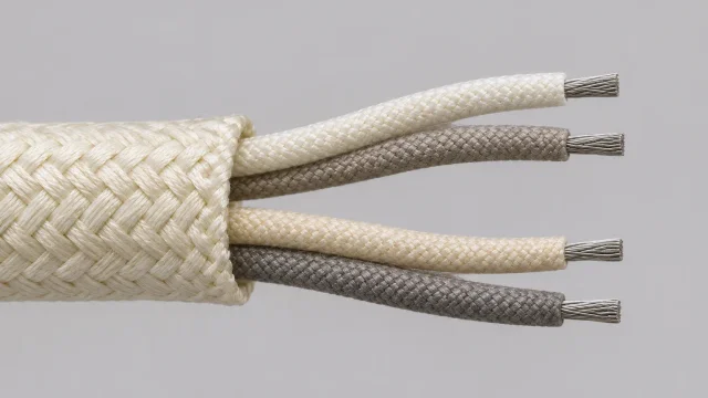
A boiler drawing may show 700°C at a thermocouple tip and give no temperature for the cable leaving the probe head. Quoting both for the same exposure can leave the real hot spot, the position of the first connector and the required measurement accuracy undefined.
An anonymized boiler instrumentation inquiry illustrates a harder case: Type K cable with four insulated 1.0 mm² cores arranged in two independent pairs, high-temperature fiberglass insulation and a requested cable exposure of up to 700°C. To evaluate that request, define where the cable gets hot, for how long, and how much measurement error the two circuits can tolerate.
What Is a High-Temperature Type K Thermocouple Cable?
A Type K measuring junction joins two dissimilar nickel alloys. Nickel-chromium, NiCr (Chromel), is the positive leg; nickel-aluminium, NiAl (Alumel), is the negative leg. The instrument interprets the resulting thermoelectric voltage using the temperature of its reference junction or cold-junction compensation. IEC 60584-1 and the NIST Type K reference tables describe the reference relationship between temperature and voltage.
Thermocouple-grade wire can form the measuring junction and is selected for the probe’s intended measurement duty. KX extension cable uses the same nominal alloy compositions and has specified tolerances over a defined extension-cable temperature range. Compensating cable uses different alloys chosen to approximate the thermocouple response over its own specified range. Even with similar-looking insulation, these grades are not interchangeable.
An ordinary copper pair can introduce error when it moves the Type K-to-copper transition away from the point where the instrument senses the reference temperature. Copper can be appropriate downstream of a field transmitter that already measures and compensates the thermocouple signal. For a cooler extension run, see the K-Type thermocouple extension cable selection guide.
Understanding the 4-Core, 2-Pair Construction
Four cores describe the physical count. Two pairs describe the electrical arrangement: Pair 1 has its own NiCr (+) and NiAl (−) conductors for Channel 1, and Pair 2 has a second NiCr (+) and NiAl (−) set for Channel 2. Each conductor has individual insulation. The pairs have no shared return within the cable. Verify channel assignment as well as polarity when terminating and checking the two loops.
Specify a durable pair identifier alongside the applicable polarity convention so a technician can identify both legs of each pair after removing the outer covering. If the design calls for twisting, twist each positive/negative pair independently and document its lay in the approved drawing. Twisting can reduce pickup from external magnetic fields, but shielding is a separate decision. If screening is required, specify individual or overall screens, temperature suitability, isolation and bonding. A mechanical overbraid or armour also needs its own specification.
Example Custom 4-Core Type K Cable Requirements
This table describes a procurement example for engineering review. It does not establish a released construction, rating or certification.
| Parameter | Example requirement |
|---|---|
| Thermocouple type | Type K |
| Nominal conductor alloys | NiCr (+) and NiAl (−); exact grades to be confirmed |
| Number of cores | Four individually insulated signal conductors |
| Number of pairs | Two electrically independent Type K circuits |
| Nominal conductor size | 1.0 mm² per conductor |
| Conductor construction | Solid or stranded; to be confirmed |
| Pair arrangement | Two identified pairs; individual twist and lay if specified |
| Core insulation | High-temperature fiberglass; grade and wall to be confirmed |
| Requested cable exposure | Up to 700°C; duration and exposure conditions to be confirmed |
| Overall protection | Project-specific; no shield or armour assumed |
| Thermoelectric grade and tolerance | To be confirmed for the intended temperature profile |
| Application | Industrial boiler instrumentation |
Why High-Temperature Fiberglass Insulation?
Ordinary PVC cannot retain its insulation function under direct 700°C cable exposure. Fiberglass braid offers a candidate for hotter conditions, but “fiberglass” describes a material family. Conventional glass fibre and special high-temperature glass fibre systems cannot be substituted on name alone. Check the fibre grade, wall thickness, braid coverage, and any binder, finish or coating. An overall glass braid can hold the bundle together and protect the core insulation; it does not make porous insulation waterproof or act as an electrical screen.
| Insulation family | When to consider it |
|---|---|
| PVC | Cooler routes within the finished cable rating; unsuitable for direct 700°C exposure. |
| PFA | Cooler sections needing a smooth extruded finish or chemical resistance. Consult the fluoropolymer insulation guide for selection factors. |
| Conventional fiberglass | Hotter, appropriately protected routes where the specific glass system suits the exposure. |
| High-temperature fiberglass | Hot sections that exceed the capability of the proposed conventional insulation. Confirm every layer for the actual duty. |
Check how the braid behaves when pulled around supports or stripped for termination. Sharp edges, rubbing and repeated bending can fray it and reduce separation between cores. Moisture, soot and conductive deposits can also lower insulation resistance. Binders and coatings can affect handling and moisture resistance before and after heating; review their limits along with the fibre itself. Tempco’s insulation construction notes illustrate how finishes and construction affect these trade-offs.
What Does a 700°C Cable Requirement Actually Mean?
Separate these temperatures before specifying the cable:
- Process and measuring-junction temperature. The process value describes the gas, liquid or surface being measured. The tip can be at a different temperature if insertion depth, heat transfer or transient conditions affect the measurement.
- Cable ambient and conductor temperature. Ambient air is only one heat source. Radiation from hot boiler surfaces and conduction from metal supports can raise local cable temperatures. Identify hot lengths, normal operation and excursions.
- Insulation capability. Confirm what the fiberglass system can withstand for the exposure duration, atmosphere and mechanical duty. The insulation figure alone does not qualify the conductors or terminations.
- Thermoelectric tolerance. IEC 60584-3:2021 specifies a KX tolerance validity range of −25°C to +200°C. This is a range for the extension cable’s specified tolerance, separate from the temperature the probe measures. Heat-resistant braid cannot extend that tolerance range to 700°C.
- Complete assembly limits. Review all layers and interfaces, including pair markers, any protective covering, connector contacts, glands and terminal blocks. Their local limits can dictate where the cable changes construction or terminates.
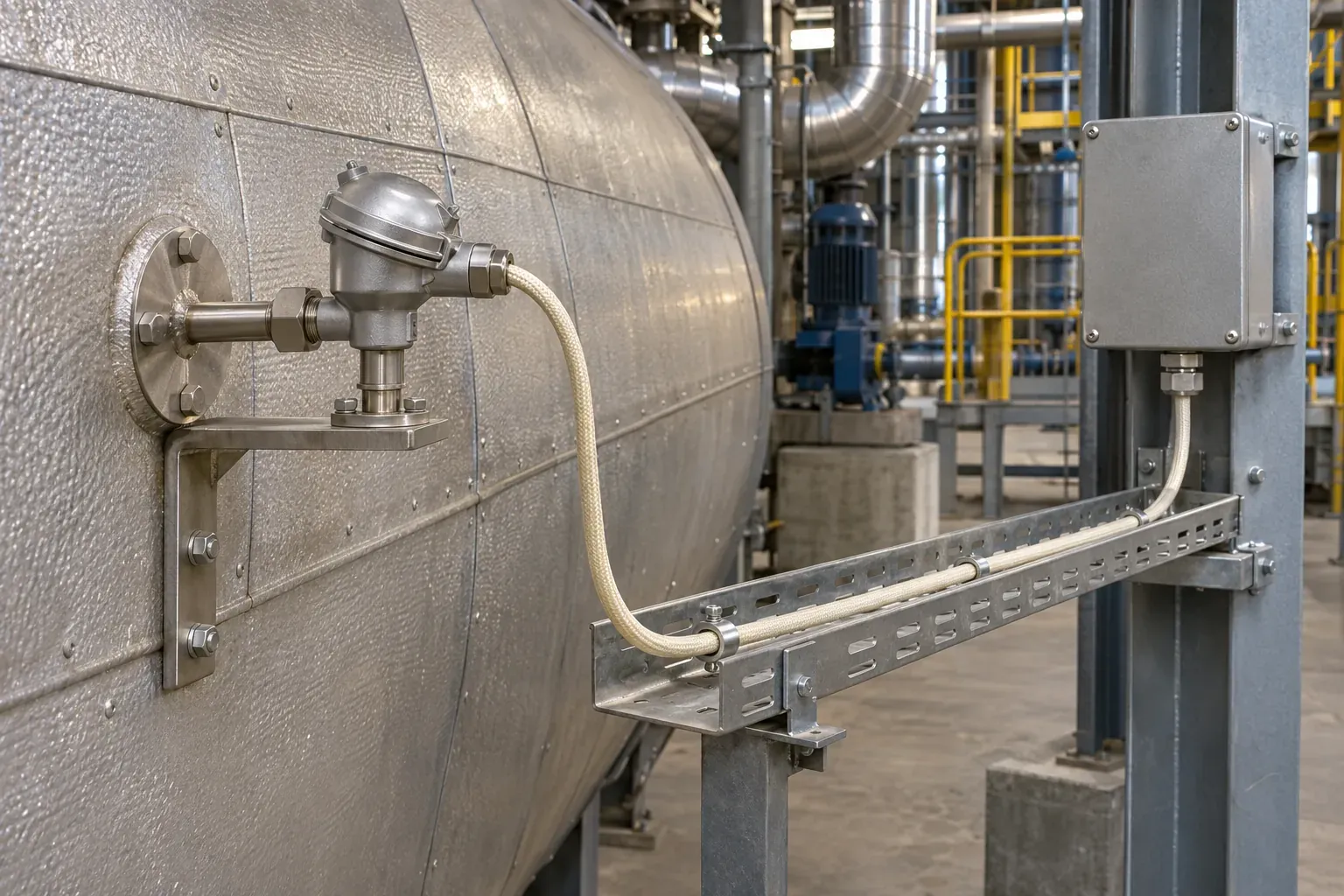
In a boiler, a probe can measure flue gas near 700°C while its head sits outside the insulated casing. The cable may still cross a short zone heated by a nearby flange before it reaches a cooler junction box. Check temperatures at the exit, supports and terminations during operation and relevant transients. If a section exceeds the temperature limits of the extension grade or assembly, review the hot-side conductors and insulation separately and place the transition where both systems can operate within their limits.
Choosing 1.0 mm² Type K Conductors
Specify 1.0 mm² of nominal metallic cross-section for each of the four conductors. Standard 20 AWG has a nominal area of about 0.518 mm², according to NBS wire tables, Table XV. A reference notation such as 2×20 is not proof of either gauge or pair count. Ask for the reference drawing if useful, then quote the explicitly approved four-conductor requirement.
Solid conductors can suit fixed routes with compatible terminals; stranded conductors are generally easier to route around bends. Confirm strand construction, diameter over insulation, bend radius and clamp or connector capacity. For long runs, ask for resistance per unit length for each alloy, then check the sum of both legs against the instrument’s allowable loop resistance under operating conditions. The two alloys have different resistivities, so a copper resistance table will not answer that question.
Custom Type K Cable Design for Industrial Boilers
The factory reviewed the 700°C requirement for the anonymized inquiry. DEV CABLE lists factory-stated upper figures of 704°C for two identified HH-series high-temperature fiberglass models. Those model figures alone do not establish the operating rating, exposure basis or measurement tolerance of this four-core proposal.
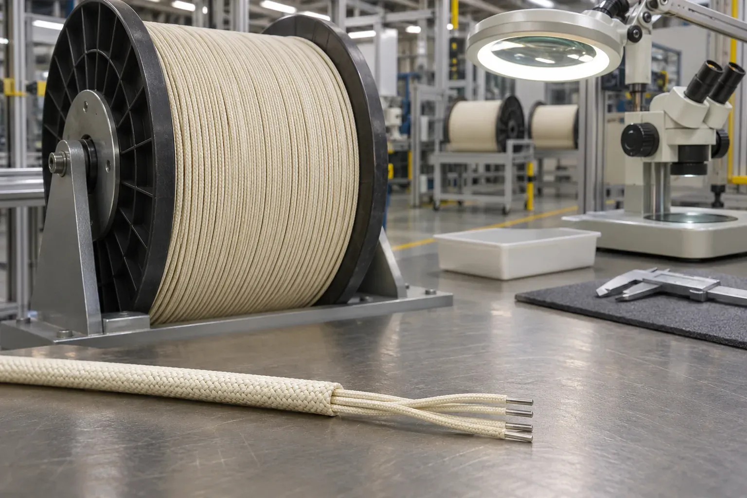
Start the design review with the route temperature profile, alloy grade and allowable measurement error. Then compare constructions for the anticipated abrasion, vibration, deposits, humidity and movement. The proposed drawing should state the four core sizes, insulation build, pair lay and identification, any protective layers, and finished dimensions and tolerances. The datasheet should identify the basis for thermal and electrical limits, acceptance tests and approximate cable weight. Confirm cut lengths, reel dimensions, packed weight and handling needs separately for shipping. All remain subject to design agreement in this example.
How to Request a Custom Thermocouple Cable Quotation
Send enough information for the supplier to quote the same design your installer and instrument engineer expect:
- Measurement: Thermocouple type, conductor grade, applicable standard and edition, required tolerance and where it must hold.
- Conductors: Core count, pair count, cross-sectional area per core, solid or stranded construction and termination constraints.
- Route and exposure: Continuous and peak temperatures, peak duration and frequency, location of hot sections, moisture, contamination, abrasion and movement.
- Cable build: Core insulation, pair lay, identification standard and pair markings, electrical screening and bonding, and any mechanical protection.
- Supply: Total quantity, individual cut lengths or lengths per reel, packaging, delivery location and agreed Incoterms rule and named place.
- Acceptance: Required drawings, datasheet, test methods, acceptance criteria and reports. Distinguish checks for continuity, insulation integrity and thermoelectric performance.
Why Choose DEV CABLE for Custom Thermocouple Cables?
DEV CABLE reviews project specifications and manufactures custom cables for international industrial buyers. Options for review include multiple conductor sizes, multi-pair layouts and high-temperature insulation systems. Open the custom thermocouple extension cable page and select Request a Custom Cable Quotation to send the cable schedule and temperature profile for review.
Frequently Asked Questions
Can Type K thermocouple cable withstand 700°C?
Some constructions are candidates for that exposure. Confirm the finished cable’s thermal limits for the stated duty and specify thermoelectric performance separately. The IEC KX tolerance range ends at +200°C.
What is the difference between 4-core and 2-pair thermocouple cable?
Four-core gives the number of insulated conductors. Two-pair tells you how those conductors are grouped. In this Type K design, each identified pair contains one NiCr positive conductor and one NiAl negative conductor.
Can I order Type K cable with 1.0 mm² conductors?
Yes, as a custom requirement subject to design review. State 1.0 mm² per conductor, and provide the required stranding, terminal constraints and duty.
Is fiberglass insulation better than PFA for high-temperature applications?
A suitable fiberglass system may serve where exposure exceeds the proposed PFA cable’s limits. PFA can suit cooler sections that benefit from an extruded insulation layer. Check heat, moisture and abrasion against the complete cable design.
What specifications are needed for a custom Type K cable quotation?
Start with the grade and tolerance, core and pair layout, conductor area, thermal profile and insulation. Include routing and termination drawings if available, plus lengths, destination and acceptance requirements.