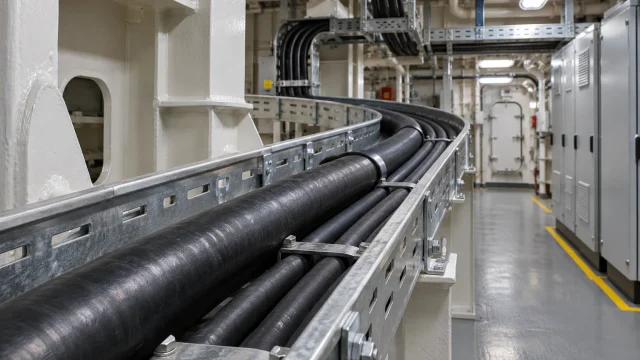
Introduction: Understanding EMC Shipboard Power Cables
An EMC shipboard power cable carries electrical power and uses a conductive screen to help control electromagnetic coupling. In a machinery space, a feeder from a variable-frequency drive may run near sensor, control or communications circuits. Switching signals can couple into nearby wiring and disrupt those circuits. The cable screen, terminations, bonding and routing all contribute to electromagnetic compatibility (EMC).
Reliable shipboard distribution depends on both circuit design and the cable’s suitability for its route. Machinery spaces may impose vibration, tight bends, grouped tray runs and demanding installation conditions. Procurement also needs to account for marine construction rules, fire and smoke requirements, and the vessel’s classification requirements. Each of these can affect whether a proposed cable is acceptable for a fixed installation.
An anonymized request for quotation (RFQ) called for a customized three-core 0.6/1 kV marine power cable. The buyer supplied a reference construction and required EMC screening, halogen-free construction, low smoke emission and flame retardancy.
| Parameter | Reference specification |
|---|---|
| Cable type | EMC shipboard power cable |
| Rated voltage | 0.6/1 kV |
| Design standard | IEC 60092-353 |
| Configuration | 3 × 300 mm² |
| Conductor | Class 5 annealed bare stranded copper |
| Insulation | XLPE |
| Shielding | Copper polyester tape and bare copper wire braid |
| Braid coverage | ≥90% |
| Outer sheath | SHF1 halogen-free compound |
| Requested approvals | DNV / BV / LR |
These are project-specific requirements. The final construction and the scope of each applicable approval are subject to design and certificate review.
IEC 60092-353: Requirements for Marine Power Cables
IEC 60092-353:2024, the fifth edition, covers shipboard and offshore non-radial-field power cables for fixed installations. It applies to cables with extruded solid insulation at 0.6/1 (1.2) kV and 1.8/3 (3.6) kV. In this voltage notation, the first value is the rated conductor-to-earth voltage, the second is the rated conductor-to-conductor voltage and the value in parentheses is the highest system voltage for which the cable is designed.
Three complementary standards help translate an IEC 60092-353 cable requirement into a construction and test specification.
- IEC 60092-350:2020 provides general construction requirements and test methods for shipboard and offshore power, control and instrumentation cables. Apply any specific provisions in IEC 60092-353 that govern the offered power cable.
- IEC 60092-360:2021 defines requirements for insulating and sheathing materials used in marine and offshore cables, including electrical and mechanical properties as applicable to the material type.
- IEC 60228:2023 specifies nominal conductor sizes, construction requirements and resistance limits for the relevant conductor class.
Specify cable construction compliance and EMC acceptance separately. IEC 60092-353 addresses collective metallic screen constructions where applicable. If a project needs measured shielding performance, define the test method, frequency range, termination arrangement and acceptance criteria in the RFQ.
Fixed installations can experience ship motion and vibration. Class 5 stranding eases cable handling during installation. Frequent or continuous flexing calls for a cable design qualified for that duty.
Construction of a 0.6/1kV EMC Shipboard Power Cable
The reference specification identifies six elements. The final construction drawing should show how the cores, tapes and braid are assembled.
| No. | Component | Material | Main function |
|---|---|---|---|
| 1 | Conductor | Annealed bare stranded copper, Class 5 | Carries load current |
| 2 | Insulation | Cross-linked polyethylene (XLPE) | Electrically isolates each conductor |
| 3 | Bedding | Polyester tape | Separates and protects adjacent layers |
| 4 | Screening tape | Copper polyester tape | Forms part of the metallic screen |
| 5 | Braid | Bare copper wire braid | Adds screen coverage and continuity |
| 6 | Outer jacket | SHF1 compound | Protects the cable assembly |
Copper Conductor
In 3 × 300 mm², each of the three cores has a nominal conductor cross-sectional area of 300 mm². Annealed copper combines high conductivity with ductility, and the fine wires in a Class 5 conductor make a large section easier to handle in a fixed route. Check the maximum DC resistance at the specified reference temperature for the conductor class and use the supplier’s data to assess voltage drop and losses. Verify that the terminal system accepts the strand construction.
XLPE Insulation
Cross-linked polyethylene provides dielectric separation between the conductor and adjacent materials. Cross-linking helps the insulation retain dimensional stability at elevated temperatures. Confirm the XLPE material requirements under IEC 60092-360 and the specified insulation thickness and electrical tests for the complete design. The PVC, PE and XLPE insulation guide explains how these materials compare.
Polyester Tape Bedding
The plain polyester tape separates the core assembly from the next layer and provides bedding for the screen. Its function is to help hold and protect the assembly during manufacture. The conductive screen starts at the metallic components.
Copper Polyester Tape
A copper layer bonded to polyester forms part of the screen. The reference identifies the laminate material. Engineering should confirm where it sits in the assembly, which way the conductive face is oriented and how it contacts the other screen elements.
Bare Copper Wire Braid
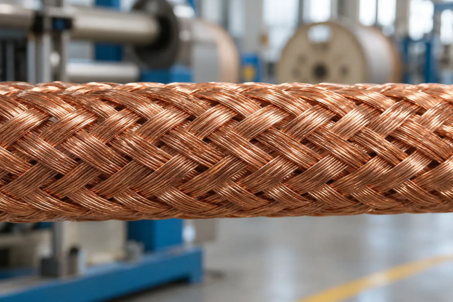
Interwoven copper wires provide conductive paths along and around the cable. The braid contributes to screen continuity and provides a layer that can be contacted by compatible glands or clamps. Specify both the braid construction and the required continuity through the terminations.
SHF1 Outer Sheath
SHF1 is a halogen-free marine sheathing compound type. The outer sheath protects the underlying layers during handling and service. Specify any additional mechanical or environmental properties for the actual route and ask for supporting data for the offered compound and cable.
Why Copper Tape and Copper Braid Shielding Matter for EMC
Copper Polyester Tape
A lapped copper laminate can cover openings between the braid wires. The tape’s contribution depends on its continuity around the assembly and on the electrical contact between wraps and other parts of the screen. Use the final drawing to verify the overlap, laminate thickness and conductive-face orientation. Confirm whether the specified screen construction requires a drain wire and how that wire would contact the screen.
Bare Copper Wire Braid
Bare copper braid adds a conductive path and can provide circumferential contact at a correctly sized EMC gland or clamp. Check how the shield connects to each enclosure and how electrical continuity is maintained through the termination. At higher frequencies, a long, narrow bonding lead can add impedance. Use the equipment supplier’s EMC instructions and the vessel bonding plan to specify the termination arrangement and keep that arrangement consistent with the test basis.
Understanding 90% Copper Braid Coverage
The reference RFQ requires at least 90% braid coverage. Coverage helps define a repeatable braid construction, and the result depends on the method used to evaluate it. IEC 60092-350:2020 gives a method for evaluating braid armour coverage density. For this cable, confirm whether the braid serves as screening, armour or both and agree on the coverage method and acceptance criteria for that construction.
Shielding performance depends on electrical continuity, frequency, screen geometry and terminations. If the purchase specification calls for attenuation in decibels or a transfer impedance limit, agree on the measurement method and request applicable test data for the proposed cable.
XLPE Insulation and SHF1 Halogen-Free Sheathing
Insulation and sheathing are specified at the material level. For the complete cable, verify which tests and acceptance criteria apply to the project.
| Material or standard | Main purpose |
|---|---|
| XLPE | Electrical insulation around each conductor |
| SHF1 | Halogen-free marine outer sheath |
| IEC 60092-360 | Requirements for marine insulating and sheathing materials |
| Required characteristic | Test reference and what it evaluates |
|---|---|
| Halogen acid gas | IEC 60754-1 determines the amount of halogen acid gas other than hydrogen fluoride released by cable materials under the test conditions. |
| Combustion gas acidity | IEC 60754-2 assesses combustion gases using pH and conductivity measurements. |
| Low smoke emission | IEC 61034-1 describes the test apparatus. IEC 61034-2 gives the test procedure and requirements using light transmittance. |
| Single-cable flame retardancy | IEC 60332-1-2 tests vertical flame propagation on a single cable or insulated conductor. |
| Bunched-cable flame propagation | IEC 60332-3-22 Category A tests vertical flame spread on a defined bundle of cables. |
Gas composition, smoke density and flame spread are separate properties. Specify the editions accepted by the project and check that the applicable reports cover the proposed materials or finished cable under the relevant test. An SHF1 designation identifies the sheath compound type. For another example of a low-smoke, halogen-free power cable construction, see RZ1-K and N2XH LSZH cables.
DNV, BV and LR Type Approval for Marine Cables
Classification society rules help determine which approval and verification documents a vessel project requires. The RFQ listed three societies for review.
| Classification society | Full name | Role |
|---|---|---|
| DNV | DNV | Marine classification and product approval |
| BV | Bureau Veritas | Marine classification and product approval |
| LR | Lloyd’s Register | Marine classification and product approval |
What Is Marine Cable Type Approval?
Type Approval assesses a product design or family for repeat manufacture within a defined scope. Product certification, where required, verifies the product supplied and can involve a survey or review of test records. Confirm the document requirements with the project’s classification society before ordering. DNV certification of materials and components
What Should Buyers Check on a Marine Cable Certificate?
Start with the certificate holder, manufacturer and stated production location. Then compare the certificate schedule and validity period with the engineering proposal. Verify the product family, rated voltage, number of cores, conductor size and class, insulation and sheath materials, and the covered screen construction. Check any certificate conditions, limits or attached schedules. If a buyer requires DNV, BV or LR approval, verify the relevant certificate scope for that society and manufacturing site.
DEV CABLE Marine Cable Manufacturing Capability
DEV CABLE manufactures custom marine power cables for project requirements. Options include large-section Class 5 copper conductors, XLPE insulation, combined copper tape and braid screening, and SHF1 sheathing. DNV, BV and LR certification documents are available for the applicable approved scopes. DEV CABLE submitted the relevant documentation for this RFQ for customer review. Confirm coverage of the exact design, size, voltage and production site before release. View the Shipboard Power Cable product page.
Key Considerations When Ordering 3 × 300 mm² Marine Power Cable
Conductor Size and Electrical Requirements
Check the proposed 300 mm² conductors against the load current and permissible voltage drop over the routed length. Use the expected operating temperature and cable impedance for the voltage-drop assessment. Ampacity depends on the installation method, ambient temperature, cable grouping and heat dissipation. For short-circuit withstand, check the prospective fault current and protective-device clearing time against the cable’s thermal limit.
Cable Installation and Bending Radius
Obtain the finished diameter, weight per metre and minimum bending radius for pulling and final placement. Check tray loading, clearances, entry geometry and space at bends. Specify cleats compatible with the cable diameter and expected forces, glands that fit the outer sheath and screen, and lugs compatible with the fine-stranded copper and available terminal space. Check the route and supports against the applicable marine installation requirements. IEC 60092-352:2025
Cable Length and Drum Packaging
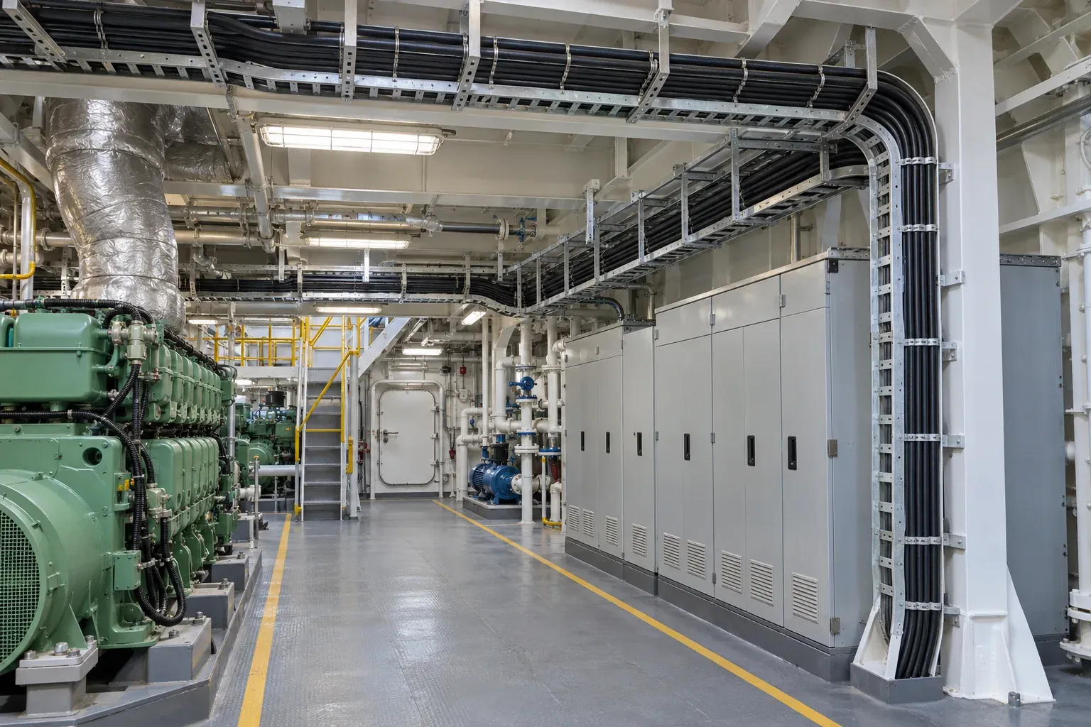
List the required continuous lengths and agree on the manufacturing length tolerance per drum. Check drum dimensions, gross weight and winding direction against transport, lifting and cable-pulling arrangements. Specify cable-end sealing, export packaging and delivery requirements before production.
Certification and Documentation
Agree on the evidence package at quotation. It can include applicable Type Approval documents, routine test reports, relevant type test reports, material and performance records, and agreed inspection or witness points. Request traceability from the drum identification to the production batch and test records. Specify which documents need approval before manufacture or shipment.
How to Specify an EMC Shipboard Power Cable
Use the reference construction below as a starting point for an RFQ. Add the information that controls the installation and the acceptance of the finished cable.
| Parameter | Example |
|---|---|
| Cable type | EMC shipboard power cable |
| Rated voltage | 0.6/1 kV |
| Standard | IEC 60092-353:2024 |
| Configuration | 3 × 300 mm² |
| Conductor | Class 5 annealed bare stranded copper |
| Insulation | XLPE |
| Bedding | Polyester tape |
| Screening tape | Copper polyester tape |
| Braid | Bare copper wire |
| Braid coverage | ≥90%, with method to be agreed |
| Outer sheath | Halogen-free SHF1 |
| Temperature | −40 °C to +90 °C in the reference construction, subject to the approved design |
| Classification approval | DNV / BV / LR, as required by the project |
| Quantity | Project-specific |
| Installation | Fixed marine installation |
For a complete RFQ, provide the installation environment, continuous lengths, destination and documentation requirements. Clarify the temperature basis for the proposed cable, including the minimum installation temperature, operating ambient and maximum conductor temperature. Include the equipment interfaces and agreed EMC, halogen, smoke and flame acceptance tests. Confirm any missing details against the offered drawing, datasheet, test reports and applicable certificates before ordering.
References and Technical Standards
Use the official standards and the applicable product certificates and schedules for formal project compliance.
- IEC 60092-353:2024 for marine power cable construction and testing.
- IEC 60092-350:2020 for general construction and test methods.
- IEC 60092-360:2021 for insulating and sheathing materials.
- IEC 60228:2023 for conductor classification and requirements.
- DNV Approval Finder, BV Approval Explorer and Lloyd’s Register Approvals for checking approval records.