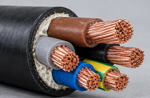
DEV CABLE’s shipboard power cable enquiry page is for shipyards, marine electrical contractors, ship repair operators, marine system integrators and distributors specifying 0.6/1 kV cables for fixed installations. Start with the vessel’s electrical design and cable schedule, then confirm the construction and evidence for each proposed model.
IEC 60092-353:2024 covers fixed shipboard and offshore power cables at both 0.6/1 kV and 1.8/3 kV. This launch page focuses on 0.6/1 kV marine power cable. A reference to the standard does not establish that every material, core arrangement or armour combination has been approved. Final compliance depends on the selected cable model, its documented construction and the applicable project requirements.
Available Sizes & Cable Dimensions
DEV CABLE manufactures to project-specific core counts, conductor cross-sections and cable constructions. Specify the insulation, armour and sheath needed for your installation. The table shows custom configuration examples, not a closed catalogue; other core counts and conductor sizes can be specified in your RFQ. Final dimensions and weight depend on the agreed construction, and any classification approval must match the selected model.
| Cable Type / Construction | No. of Cores | Conductor Cross-section (mm²) |
|---|---|---|
| Custom single-core shipboard power cable | 1 | 1.5 |
| Custom 2-core shipboard power cable | 2 | 2.5 |
| Custom 3-core shipboard power cable | 3 | 16 |
| Custom 4-core marine power cable | 4 | 25 |
| Custom 5-core cable — specify circuit duty | 5 | 1.5 |
| Shipboard control cable — separate model review | 37 | 2.5 |
To request a quotation, please specify the required number of cores, conductor cross-sectional area, insulation, armour, sheath material, applicable classification society approval and order quantity.
For a 3 × 16 mm² marine power cable, specify three conductors of 16 mm² each along with the required construction. For a 5-core cable, identify the power or control duty and any protective and neutral conductors. The 37-core example is for shipboard control enquiries and needs a separate model, construction and approval review; it is not an ordinary power-distribution variant. The table does not imply stock availability or type approval of every custom configuration.
Typical shipboard applications
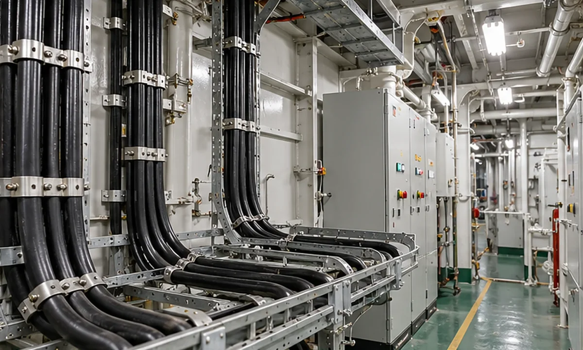
- Power distribution: fixed feeders between shipboard distribution equipment and connected circuits, as defined by the vessel’s electrical design.
- Auxiliary systems: fixed power connections for onboard equipment; confirm the installation area and equipment duty.
- Lighting circuits: fixed lighting supplies where voltage, cable construction and fire-performance requirements match the specified circuit.
- Ship repair and refit: replacement shipboard electrical cable selected against the existing cable designation, route and required documentation, rather than appearance alone.
Installation in machinery spaces, exposed areas or locations with oil, moisture or other environmental stresses requires a model with documented suitability. Emergency circuits that must continue operating during a fire need a specifically evidenced circuit-integrity construction. This fixed-installation family must not be assumed suitable for repeated reeling, continuous flexing, an ROV tether or permanent subsea immersion.
Cable construction
The following is a construction selection guide, not a list of universally available or certified combinations. Confirm the complete layer sequence on the proposed model drawing and datasheet.
| Layer | Configuration to specify | Selection purpose |
|---|---|---|
| Conductor | Stranded bare or tinned copper; core count, conductor size in mm² and stranding | Match the electrical design, terminals and required conductor specification. |
| Core insulation | XLPE as a primary example; EPR for a separately confirmed alternative | Identify the actual insulation compound and its documented ratings. Material names alone do not establish cable performance. |
| Core assembly | Single-core or laid-up multicore design; identification, fillers and binders where required | Confirm the core arrangement and identification against the cable schedule. |
| Bedding or inner covering | Included where required by the construction | Confirm the layer beneath the braid and its compatibility with the complete cable design. |
| Metallic braid | Omitted for an unarmoured design, or a suitable specified braid for an armoured version | Agree the metal, protective function and termination requirements; do not assume a braid is a verified EMC screen. |
| Outer sheath | SHF1 or SHF2, depending on the selected construction | Match the sheath compound to the installation environment and model documentation. |
SHF1 versus SHF2 outer sheath
SHF1 and SHF2 identify different halogen-free sheathing material types. SHF1 is thermoplastic; SHF2 is thermosetting (crosslinked). They describe sheath materials, while XLPE and EPR in the construction table describe core insulation. These choices must be assessed as part of the complete cable.
| Sheath type | Material distinction | What the buyer should verify |
|---|---|---|
| SHF1 | Halogen-free thermoplastic compound | The exact model’s suitability for the area, temperature, handling and expected fluid exposure. |
| SHF2 | Halogen-free thermosetting, crosslinked compound | The selected compound’s documented environmental performance and the model’s approval scope. |
Do not infer oil, drilling-mud, UV, immersion or fire-resistance ratings from a sheath designation alone. If oil or other fluids are present, specify the substance, exposure and operating conditions. Changing the sheath can change the model designation and documentation needed for acceptance.
Armoured versus unarmoured selection
Select mechanical protection from the cable route and vessel requirements, then confirm the exact construction. A braid is not a substitute for checking the installation design.
| Selection | Appropriate question | Confirmation before ordering |
|---|---|---|
| Unarmoured | Does the route and its external protection permit an unarmoured cable? | Check supports, handling, exposure to damage, glands and the accepted cable model. |
| Metallic braid-armoured | Is a braid required by the route or project specification? | Identify the braid metal, bedding, outer covering, bonding and termination arrangement. |
| Electrical screening or earthing duty | Is the braid expected to perform an electrical function as well as provide protection? | Require evidence for that function. A protective braid does not automatically establish EMC performance or protective-conductor suitability. |
For single-core AC circuits, have the armour material and installation arrangement checked for the intended electrical duty. Do not substitute an armoured model simply because its conductor size matches the schedule. Confirm the ordered diameter, bend radius and gland compatibility from the model datasheet rather than using a generic family value.
Standards, testing and certification
Keep the product specification, test requirements and classification society acceptance separate. The references below explain the standards framework; they are not a list of DEV CABLE certificates.
| Reference | Role in a shipboard cable specification |
|---|---|
| IEC 60092-353:2024 | Product requirements for fixed shipboard/offshore power cables in the standard’s voltage scope; this page addresses 0.6/1 kV. |
| IEC 60092-350:2020 | General construction requirements and test methods for power, control and instrumentation cables in fixed shipboard/offshore systems. The linked IEC listing is the redline edition. |
| IEC 60092-360:2021 | Insulating and sheathing material requirements. |
| IEC 60092-352:2025 | Selection, installation and operating conditions for cables in ships. |
Specify the editions required by the contract and classification society. A current catalogue reference does not automatically replace the edition accepted for an existing vessel or project.
Flame-retardant versus fire-resistant performance
Flame-retardant concerns limiting flame propagation under a specified test. A single-cable test such as IEC 60332-1-2 does not establish performance for cables installed in bunches; the applicable IEC 60332-3 method must be specified when required.
Fire-resistant concerns maintaining circuit integrity during defined fire-test conditions. The IEC 60331-1 and IEC 60331-2 methods address circuit integrity with fire and mechanical shock, with different applicability. State the required method and conditions and obtain evidence for the exact cable model. A flame-retardant cable must not be described as fire-resistant solely because it limits flame spread.
Low smoke and halogen requirements are separate from circuit integrity. Include the required smoke and combustion-gas test methods, such as the applicable IEC 61034 and IEC 60754 parts, in the RFQ. Neither a material label nor a general “marine cable” description proves that every required test has been passed.
Model-specific documentation and quality control
If classification society approval is required, name the society and request documentation matching the exact model, construction and relevant size/core scope. Check the certificate’s validity and limitations alongside the proposed datasheet. Do not extend one approved model’s status to every copper, insulation, armour and sheath combination.
Every finished DEV CABLE product undergoes 100% electrical continuity testing before shipment. This confirmed quality commitment does not establish fire performance, type approval or additional test results. Agree any required routine test records, type-test evidence and project inspection documents for the order separately.
Shipboard cable RFQ checklist
Send the cable schedule and the following information when contacting a shipboard power cable manufacturer or comparing proposals. List unresolved requirements explicitly so they can be addressed before the model is accepted.
| RFQ input | Information to provide |
|---|---|
| Voltage and circuit | Required U0/U rating of 0.6/1 kV, circuit function and relevant system requirements. |
| Core count and size | Number of cores, conductor size in mm², earth/neutral requirements and core identification. |
| Conductor | Bare or tinned copper and required stranding or conductor specification. |
| Insulation and sheath | XLPE requirement or confirmed EPR alternative; SHF1 or SHF2 sheath and any additional material requirements. |
| Armour and protection | Unarmoured or metallic braid, required metal, mechanical protection, bonding, glands and termination constraints. |
| Fire, smoke and halogen | Required flame-spread, circuit-integrity, smoke and halogen performance, with applicable methods and acceptance conditions. |
| Installation and operation | Vessel/project, area, fixed routing, ambient and operating conditions, fluid exposure and installation constraints. |
| Standards and documents | Applicable editions, classification society, exact-model approval requirements, datasheets and required test/inspection records. |
| Cable schedule and quantity | Each cable designation, total quantity and required cut lengths. |
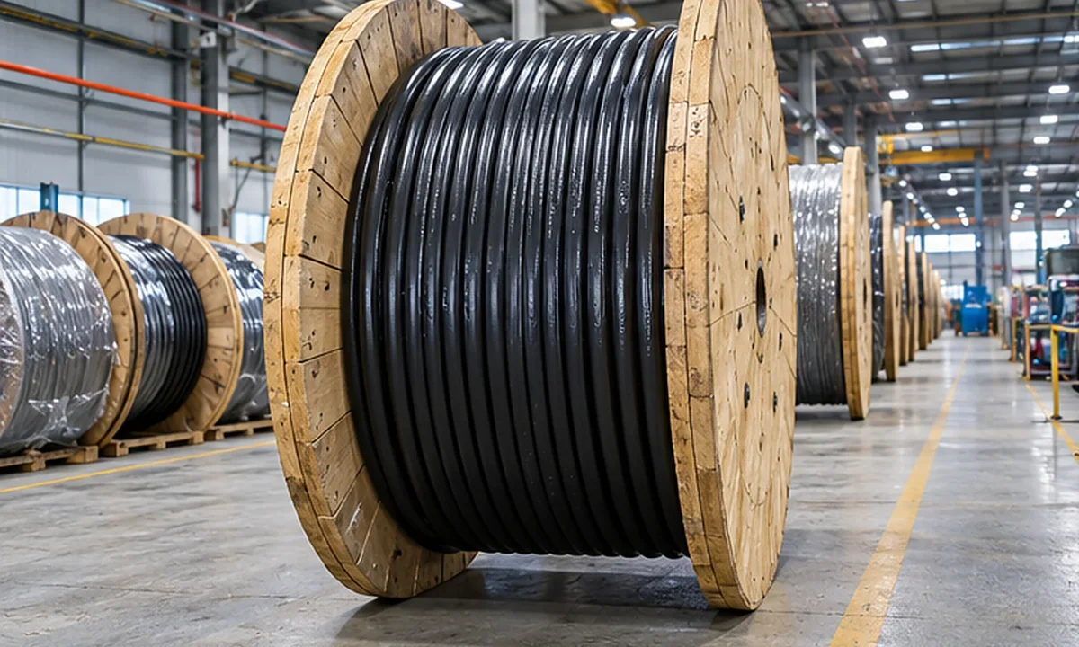
| Packing and destination | Reel or packing requirements, delivery country/port and requested delivery date for confirmation. |
Conductor size and voltage alone do not determine current capacity. The electrical designer must account for the selected cable ratings and installation conditions. Obtain model-specific diameter, weight, bend radius and temperature data before finalizing the route and terminations. MOQ and production or delivery timing require quotation-time confirmation.
Frequently asked questions
Does IEC 60092-353 only cover 0.6/1 kV cable?
No. IEC 60092-353:2024 also covers the 1.8/3 kV range. This product page focuses on 0.6/1 kV fixed shipboard power circuits; a higher-voltage requirement needs a separate model review.
Can I specify XLPE or EPR insulation?
XLPE is the primary construction example here. EPR can be discussed as an alternative only when that construction is confirmed. Check the complete model, ratings and required approval scope; the insulation types are not automatically interchangeable.
What is the difference between SHF1 and SHF2?
SHF1 is a halogen-free thermoplastic sheath type; SHF2 is a halogen-free thermosetting, crosslinked sheath type. Select using the actual environment and documented compound/model performance. Neither name alone establishes every oil, temperature or fire requirement.
Is a flame-retardant marine cable also fire-resistant?
Not automatically. Flame retardance addresses flame propagation, while fire resistance addresses circuit integrity under specified test conditions. For an emergency circuit, specify the required circuit-integrity method and request evidence for that model.
Are all configurations covered by a classification certificate?
No blanket approval is claimed. Certification must match the exact selected cable model and the scope stated in the applicable document. Confirm coverage of the proposed construction, conductor sizes and core arrangements before ordering.
Where can I find conductor sizes, current ratings and installation limits?
Use the Available Sizes & Cable Dimensions table to identify the information to confirm, then request the datasheet for the proposed model with your cable schedule. This family page does not publish unverified size ranges, ampacity, diameter, weight, bend radius or temperature limits. Current-rating selection also depends on the installation conditions.
Can this cable replace an ROV tether or subsea cable?
This page addresses fixed shipboard installation. It does not establish continuous-flexing, buoyancy, reeling or subsea-immersion performance. For those duties, use a separately reviewed construction with the appropriate mechanical and environmental evidence.
Technical reading
The PVC, PE and XLPE insulation guide explains material distinctions relevant to the insulation discussion. The EPR, EPDM and HEPR comparison helps frame questions about a proposed rubber-insulated alternative. These guides provide material context; the selected shipboard model and project documents determine acceptance.
Use the related cable families below for adjacent applications. Sharing a marine project or a material does not make different cable families interchangeable.