ESP cable product range
ESP cable supplies three-phase power from the surface system to an electric submersible pump motor in an oil, gas or geothermal well. The correct cable is a configured system: main power cable, cable splice, motor lead extension (MLE), pothead and motor interface must match the electrical load, annular clearance and downhole environment.
Start with the well and motor data, then compare the constructions below. For a water or sewage pump, use the submersible pump cable selection page; immersion alone does not make the two cable families interchangeable.
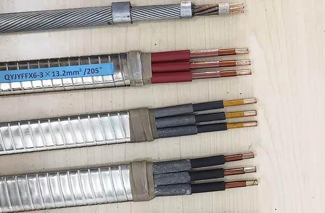
Flat ESP power cable
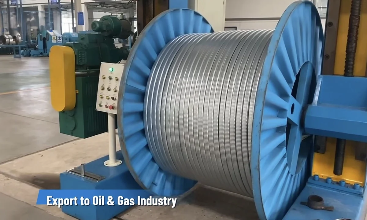
The common main downhole arrangement uses three insulated conductors side by side. Its compact, low profile suits limited clearance between production tubing and casing. Modified PP, EPDM/EPR and higher-temperature insulation systems can be combined with galvanized steel, stainless steel or Monel armor after technical review.
Round ESP power cable
Round ESP cable uses a symmetrical three-core arrangement where well geometry permits the larger radial profile. It offers balanced geometry and electrical field distribution and can use steel-tape armor. Selection still depends on clearance, running method and the complete construction.
High-temperature ESP cable
For high temperature, high gas-oil ratio or aggressive well fluids, available constructions may combine EPDM/EPR, polyimide composite or fluoroplastic insulation with a lead-alloy metallic barrier and stainless steel or Monel armor. A material name alone does not establish the continuous temperature rating.
Motor lead extension cable — MLE
The MLE connects the main ESP cable to the motor or pothead. Because it runs beside the pump and close to the motor, it is commonly specified with a compact profile, enhanced insulation, sealing and gas-resistant protection. Its termination must be designed for the selected ESP motor interface.
Main ESP power cable construction
| Layer or interface | Typical available configuration | What the buyer must confirm |
|---|---|---|
| Conductor | Three solid, stranded or compacted copper conductors | Motor voltage, current, starting duty, length and allowable voltage drop |
| Primary insulation | Modified PP, EPDM/EPR, polyimide composite or fluoroplastic system | Continuous and transient temperature plus electrical test requirements |
| Jacket or barrier | NBR, EPDM, fluoroplastic or lead-alloy metallic barrier | Oil, brine, gas, H₂S, CO₂, pressure and decompression exposure |
| Assembly | Flat or round | Tubing, casing, clamps, splice dimensions and running clearance |
| Armor | Galvanized steel, stainless steel or Monel tape | Corrosion severity, handling load and operator material specification |
| Motor interface | Main-cable splice, MLE and pothead/connector | ESP manufacturer, motor model and approved termination drawing |
QY-series ESP cable models
QY-series designations are widely used by Chinese ESP cable manufacturers. Exact construction and temperature rating may vary by manufacturer, project specification and well condition. The table is an indicative sourcing guide based on typical available constructions; every row requires confirmation on the DEV CABLE design sheet and quotation.
| Model | Shape | Typical insulation | Jacket / barrier | Armor | Indicative temperature | Typical voltage options | Typical size |
|---|---|---|---|---|---|---|---|
| QYPN | Flat | Modified PP | NBR | Galvanized steel tape | 90–96°C | 3 / 4 / 5 / 6 kV | AWG 7–1 |
| QYPNY | Round | Modified PP | NBR | Galvanized steel tape | 90–96°C | 3 / 6 kV | AWG 7–1 |
| QYEN | Flat | EPDM / EPR | NBR | Galvanized steel tape | 120–140°C | 3 / 4 / 5 / 6 kV | AWG 7–1 |
| QYENY | Round | EPDM / EPR | NBR | Galvanized steel tape | 120–140°C | 3 / 6 kV | AWG 7–1 |
| QYEE | Flat | EPDM / EPR | EPDM | Galvanized steel tape | 175–204°C | 3 / 6 kV | AWG 6–1 |
| QYEEY | Round | EPDM / EPR | EPDM | Galvanized steel tape | 175–204°C | 3 / 6 kV | AWG 6–1 |
| QYEQ | Flat | EPDM / EPR | Lead-alloy sheath | Galvanized steel tape | 150–232°C* | 3 / 6 kV | AWG 6–1 |
| QYEQX | Flat | EPDM / EPR | Lead-alloy sheath | Stainless steel tape | 150–232°C* | 3 / 4 / 5 / 6 kV | AWG 7–1 |
| QYEQM | Flat | EPDM / EPR | Lead-alloy sheath | Monel armor | Up to 232°C* | 3 / 4 / 5 / 6 kV | AWG 7–1 |
| QYYEQ | Flat | Polyimide + EPDM | Lead-alloy sheath | Galvanized steel tape | 204–232°C | 3 / 6 kV | AWG 7–1 |
| QYYEQX | Flat | Polyimide + EPDM | Lead-alloy sheath | Stainless steel tape | 204–232°C | 3 / 6 kV | AWG 7–1 |
| QYYFF | Flat | Polyimide / F46 + fluoroplastic | Fluoroplastic | Steel tape | 180–250°C* | 3 / 4 / 5 / 6 kV | AWG 7–1 |
*Temperature values are indicative, not guaranteed ratings. The final class depends on the complete insulation and barrier design, armor material, gas concentration, pressure, conductor loading, cable construction and customer specification.
ESP motor lead extension cable — MLE
Motor lead extension cable is installed between the main ESP power cable and the submersible motor. Its location near the motor can expose it to higher local temperature, oil, gas and pressure, so MLE design normally needs enhanced insulation, sealing and decompression resistance.
| Model | Application | Typical insulation | Barrier / jacket | Armor | Indicative temperature | Typical voltage options | Typical size |
|---|---|---|---|---|---|---|---|
| QYJYEQ | MLE | Polyimide + EPDM | Lead-alloy sheath | Galvanized steel | 204–232°C | 3 / 6 kV | AWG 7–2 |
| QYJYEQX | MLE | Polyimide + EPDM | Lead-alloy sheath | Stainless steel | 204–232°C | 3 / 4 / 5 / 6 kV | AWG 7–2 |
| QYJYEQM | MLE | Polyimide + EPDM | Lead-alloy sheath | Monel | Up to 232°C | 3 / 6 kV | AWG 7–2 |
| QYJYFF | High-temperature MLE | Polyimide / F46 + fluoroplastic | Fluoroplastic | Galvanized steel | Approx. 205°C+ | 3 / 4 / 5 / 6 kV | AWG 7–4 |
| QYJYFFX | High-temperature MLE | Polyimide / F46 + fluoroplastic | Fluoroplastic | Stainless steel | Approx. 205°C+ | 3 / 4 / 5 / 6 kV | AWG 7–4 |
| QYJYFFM | High-temperature MLE | Polyimide / F46 + fluoroplastic | Fluoroplastic | Monel | Approx. 205°C+ | 3 / 4 / 5 / 6 kV | AWG 7–4 |
Engineering note — pothead matching: MLE termination must match the ESP motor pothead or connector. Pothead dimensions and sealing structures vary between ESP manufacturers. Provide the motor manufacturer, motor model, connector drawing or pothead dimensions before production.
Typical ESP cable conductor sizes
| AWG size | Approximate cross-section | Typical sourcing use |
|---|---|---|
| #8 AWG | ~8.4 mm² | MLE / customized ESP |
| #7 AWG | ~10 mm² | MLE / smaller ESP systems |
| #6 AWG | ~13.3 mm² | Main cable / MLE |
| #5 AWG | ~16 mm² | Main cable / MLE |
| #4 AWG | ~21.2 mm² | Common ESP main cable |
| #2 AWG | ~33.5 mm² | Medium- or high-power ESP |
| #1 AWG | ~42.4 mm² | High-power ESP systems |
| 1/0 AWG | ~53.5 mm² | High-current customized ESP |
| 2/0 AWG | ~67.4 mm² | Large ESP systems / custom |
Metric configurations such as 3 × 10 mm², 3 × 16 mm², 3 × 20 mm², 3 × 25 mm², 3 × 33.5 mm², 3 × 35 mm² and 3 × 42.5 mm² can be evaluated against project requirements. AWG and metric values shown together are approximate sourcing references, not declarations of exact equivalence.
ESP cable insulation and temperature classes
| Cable system | Indicative temperature | General selection context |
|---|---|---|
| PP + NBR | ~90–100°C | Standard wells within the confirmed PP-system limit |
| EPDM/EPR + NBR | ~120–140°C | Medium-temperature oil wells |
| EPDM/EPR + EPDM | ~175–204°C | Higher-temperature wells |
| EPDM/EPR + lead barrier | ~150–232°C | High gas, high temperature or corrosive wells |
| Polyimide + EPDM + lead | ~204–232°C | Premium high-temperature ESP construction |
| Polyimide / F46 / fluoroplastic | ~180–250°C | High-temperature MLE and custom ESP construction |
The maximum continuous conductor and well-fluid temperatures must be confirmed from the complete cable construction, electrical loading and actual well environment. Temperature labels from different suppliers are not directly interchangeable.
Armor options for ESP cable
Galvanized steel tape armor
This common, cost-conscious option provides mechanical protection for standard wells and lower-corrosion environments. It should not be selected for a sour or corrosive well without a materials review.
Stainless steel tape armor
Stainless armor can be evaluated for H₂S, CO₂, offshore and other corrosive downhole conditions. Grade 304 or 316 may be considered when required, but “stainless steel armor” does not automatically mean 316; the alloy must be stated in the order.
Monel armor
Monel is a higher-cost option considered for severe H₂S/CO₂ exposure, high-temperature corrosive wells and premium ESP systems. Final suitability still depends on fluid chemistry, concentration, temperature, pressure and the operator materials specification.
Voltage ratings
Typical project options include 3 kV, 4 kV, 5 kV and 6 kV. 5 kV ESP cable is explicitly available for evaluation for international ESP projects. The voltage rating must be matched to the insulation thickness, motor system and applicable test specification; not every QY model supports every listed voltage. Other ratings are subject to technical confirmation.
Flat ESP cable vs round ESP cable
| Feature | Flat ESP cable | Round ESP cable |
|---|---|---|
| Installation space | Excellent for narrow annular clearance | Requires more radial clearance |
| Typical application | Most downhole ESP installations | Wells with sufficient casing clearance |
| Mechanical profile | Low profile | Symmetrical and mechanically balanced |
| Availability | Very common | Available on request |
| Main power cable | Yes | Yes |
| MLE | Mostly flat or specialized | Application dependent |
Flat ESP cable is commonly selected because it runs beside the production tubing and the clearance between tubing and casing may be limited. Round cable should not be rejected on shape alone: where clearance permits, its symmetrical construction can offer useful mechanical and electrical characteristics.
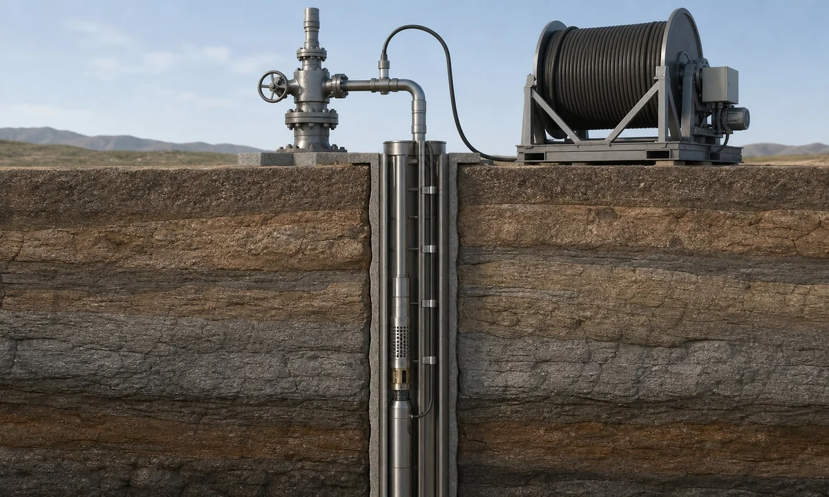
ESP cable system path
The system must be checked end to end. Cable voltage drop, splice design, MLE temperature capability and pothead sealing can each limit the completed installation.
ESP cable selection by well condition
| Well condition | General selection guidance | Confirmation required |
|---|---|---|
| Standard oil well | PP or EPDM insulation; galvanized steel armor | Actual temperature, fluid and installation loads |
| Medium-temperature well | EPDM/EPR insulation; NBR or EPDM jacket | Continuous and transient temperature |
| High-temperature well | High-temperature EPDM or polyimide composite; lead barrier where required | Complete thermal design and decompression exposure |
| H₂S / CO₂ corrosive well | Metallic barrier; stainless steel or Monel armor | Gas concentrations, water chemistry and material grade |
| High gas-oil ratio well | Gas-resistant insulation, lead-alloy barrier and high-integrity MLE termination | Pressure cycle, decompression and termination design |
| High-temperature MLE | Polyimide/F46/fluoroplastic system; stainless or Monel armor | Motor model, pothead drawing and local motor-head temperature |
This table is general screening guidance, not an engineering calculator or a final materials recommendation.
Understanding QY-series model designations
| Code | Typical meaning in many Chinese model systems |
|---|---|
| QY | Electric submersible pump cable |
| QYJ | ESP motor lead / motor lead extension |
| P | Polypropylene insulation |
| E | EPDM / EPR insulation or jacket, depending on position |
| N | NBR / nitrile rubber |
| Q | Lead or lead-alloy sheath |
| F | Fluoroplastic |
| X | Stainless steel tape armor |
| M | Monel armor |
Individual letters must be read in position within the complete designation. A final “Y” can indicate round construction in some Chinese systems, while “Y” in another position may identify a polyimide-based insulation system. Always confirm the written layer construction instead of ordering from the code alone.
Standards, testing and custom configuration
ESP cables can be designed and manufactured according to applicable GB standards, oilfield specifications and customer technical requirements, subject to confirmation for the ordered construction. IEEE 1017.2 covers specified EPR-insulated ESP cable systems and IEEE 1017.3 covers PP-insulated systems; a reference in an RFQ is not a claim that every construction is compliant or certified.
GB/T 17389-2026, Manufacture, inspection and application of electric submersible pump cable, was published on February 27, 2026 and takes effect on September 1, 2026. Until the project adopts the new edition, the applicable contract standard and transition requirements must be identified explicitly. DEV CABLE does not present GB/T 16750-2008 as the current national standard.
Custom configurations may be evaluated for flat or round geometry, three conductors, conductor size, 3–6 kV voltage, insulation system, lead barrier, armor alloy, cable length, splice and MLE interface. Feasibility, dimensions, ratings, tests, marking and documentation are confirmed on the design sheet before production. Every finished cable length undergoes 100% continuity testing before shipment; additional tests must be listed in the RFQ.
For a documented starting point, the technical-document section includes a QYEQX 3 × 16 mm² main-cable datasheet and a QYYEQ 3 × 13 mm² MLE datasheet. Compare the document’s exact construction with the requested cable; neither document establishes ratings or dimensions for the whole QY family.
Information required for ESP cable quotation
- Main ESP cable or motor lead extension (MLE)
- Flat or round cable
- Conductor size in AWG or mm² and number of conductors
- Rated voltage and motor current/power
- Required cable and MLE lengths
- Maximum downhole and motor-head temperatures
- H₂S and CO₂ concentrations, if known
- Well pressure, fluid composition and gas-oil ratio, where relevant
- Required insulation, jacket and lead-sheath/barrier system
- Armor material: galvanized steel, stated stainless grade or Monel
- ESP motor manufacturer and motor model
- Pothead/connector drawing or dimensions for MLE
- Required standards, tests, marking and inspection documents
- Quantity, reel/packing requirements and destination country
Use Send Your ESP Cable Specification below.
When comparing quotations, use the same conductor size, continuous temperature basis, voltage/test requirements, barrier, armor alloy and termination scope. Record any deviations on the design sheet before ordering; matching model names alone is not an equivalent specification.
ESP cable technical resources
- ESP cable vs motor lead extension (MLE) — main-cable and MLE roles, splice scope and motor-interface requirements.
- EPR vs EPDM vs HEPR cable insulation — insulation terminology and application-specific qualification.
- ETFE vs FEP vs PFA cable insulation — material selection and the limits of polymer temperature ratings.
- Oilfield ESP cable procurement — comparing well conditions, cable construction and procurement documents.
Frequently asked questions
What is an ESP cable?
It is the specialized three-phase power cable that feeds an electric submersible pump motor in an oil, gas or geothermal well. The cable system normally includes the main power cable, splice, MLE and motor termination.
Why are most ESP cables three conductor?
ESP motors generally use three-phase power, so the main cable normally has three power conductors. The exact motor and grounding arrangement must follow the pump-system specification.
What is the difference between ESP main cable and MLE?
The main cable covers most of the route from the wellhead toward the pump. The shorter motor lead extension connects the main cable to the motor and works in the hotter, mechanically constrained region near the pump and pothead.
What is QYEQX ESP cable?
It commonly identifies a flat ESP cable with EPDM/EPR insulation, a lead-alloy barrier and stainless steel tape armor. Temperature, voltage, conductor size, stainless grade and layer dimensions remain project-specific.
What is QYJYFFX cable?
It is a Chinese designation used for some high-temperature ESP motor-lead constructions with polyimide/F46/fluoroplastic insulation and stainless steel armor. The final MLE construction and pothead interface must be confirmed from the specification.
What voltage is commonly used for ESP cable?
3 kV, 4 kV, 5 kV and 6 kV are common sourcing options. The selected model, insulation thickness and tests must support the required system voltage.
What armor should be used in an H₂S well?
Stainless steel or Monel may be considered, but the decision requires H₂S/CO₂ concentrations, water chemistry, pressure, temperature and the operator materials specification. Stainless grade must be stated rather than assumed.
Can DEV CABLE customize ESP cable?
Conductor size, cable profile, insulation, voltage, temperature class, barrier and armor can be evaluated, together with MLE length and termination requirements. The approved design sheet defines what will be manufactured and tested.